Swap" mode, Backlighting, Unswitched inputs – PS Engineering PMA8000B Installation Manual User Manual
Page 12: Acklighting, Nswitched inputs
PS Engineering
PMA8000B Audio Selector Panel and Intercom System
Installation and Operator’s Manual
200-890-0100
Page 2-5
Rev. 13, Dec. 2009
2.4.8
"Swap" Mode
When a momentary, normally open, push-button switch is connected between pin 20 on the J2 connector
and aircraft ground, the user can switch between Com 1 and 2 by depressing this switch without having to
turn the mic selector switch. This yoke-mounted switch eliminates the need to remove your hands from
the yoke to change transceivers. The transfer of TX indication from Com 1 to Com 2 shows that the swap
has been initiated; there is no dedicated swap indicator.
2.4.9
Backlighting
The PMA8000B has an automatic dimming of the pushbutton annunciation LEDs and marker lamps con-
trolled by a photocell. Control of the unit backlighting is through the aircraft avionics dimmer For 14 V
aircraft, connect J2 Pins 6 and 7 to the aircraft dimmer bus, and pin 5 to ground. For 28-volt systems, con-
nect pin 7 to the aircraft dimmer, and pins 5 and 6 to ground.
If an external dimmer control is not used, a constant back light illumination can be established for nigh t-
time viewing. Pin 6 or 7 (depending on system voltage) must be tied to power (J2, pin 8 or 9) for the back
lighting system to work. The photocell mounted in the unit face will automatically adjust the inte nsity of
the push-button annunciator LEDs.
2.4.10 Unswitched inputs
J1, pins 31, 29 and J2 pin 15 are unswitched, unmuted (by transmitter keying), inputs # 1, 3 and 4, re-
spectively. These inputs are presented to the pilot and copilot regardless of the audio configuration, and
will always mute the entertainment inputs. These 510Ω inputs can be used for altimeter DH audio, GPS
waypoint audio, autopilot disconnect tones, or any other critical audio signal. Unswitched #1 is always
presented to the speaker, plus to the crew headphones, and is available to the pilot in fail -safe (off) mode.
Unswitched 3 and 4 inputs are always presented to the crew headphones and to the aircraft speaker.
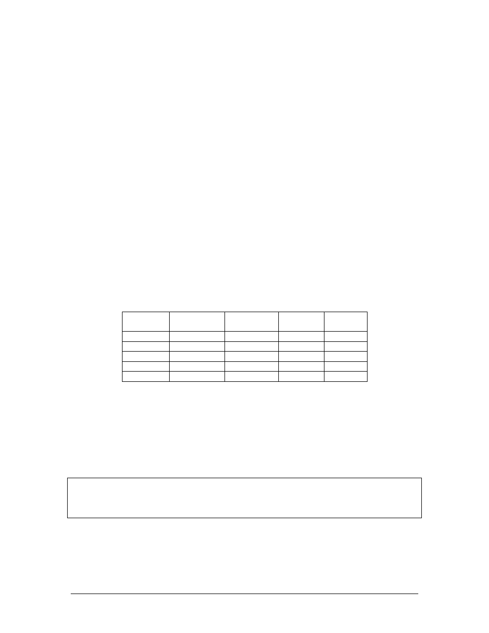
Unswitched
Input
Hear in
Fail Safe
Hear in
Crew Headset
SPR button
Select
Gain
1
Yes
Yes
No
1:1(fixed)
2
No
Yes
Yes
1:1(fixed)
3
No
Yes
No
Adjustable
4
No
Yes
No
1:1(fixed)
5 (jack)
No
Yes
No
1:1(fixed)
Table 2-2 Unswitched input table
Unswitched #2, J1 pin 44 is unswitched is always connected to the Pilot’s headphone. However, this
unswitched audio is only presented to the aircraft speaker when the SPR push button has been selected.
This input would be suitable for air-to-ground (Flitefone) telephone ringer. This input is not related to the
cellular telephone interface.
The audio low for unswitched #4 (J2, pin 15) should be connected to a convenient audio low. However,
this should NOT be connected to Music Low.
Unswitched #1 is presented to the pilot headphone in fail-safe (off) mode.
NOTE
Inputs 1, 2 and 4 are fixed (1:1), and any audio level adjustments must be made at the input source.
Unswitched #3 has a variable adjustment control located on the bottom side of the unit. This control al-
lows you to adjust the volume level of that unswitched input. Refer to Adjustments section.
The front panel jack can be configured to act as a fifth unswitched input. When configured through the
front panel function switches (see operational section), the audio input to this jack will be presented to the
pilot and copilot headsets, and not muted.