Notice – Proheat M125 User Manual
Page 75
c)
Loosen and back out the burner head mounting (2) bolts five to six turns
allowing enough room to rotate the burner head 15° counter-clockwise
and remove.
d)
Remove blower housing (2) screws and blower housing.
e)
Remove the fuse cover and using needle nose pliers or a fuse removal
tool remove the fuse.
If the fuse is blown, replace the fuse and check the PROHEAT current
draw. Go to page 4-26.
If the fuse is OK, the G-II PCM is faulty. Go to G-II PCM replacement below.
G-II PCM replacement:
a)
Disconnect the Fuel Solenoid Valve and Ignition Module connectors at
the G-II PCM.
b)
Remove the blower housing (2) screws and blower housing.
c)
Remove the blower retaining snap ring and slide the blower off the
Motor shaft.
d)
Remove the Air Compressor filter.
e)
Disconnect the Motor connector at the G-II PCM. Remove the G-II PCM.
f)
Reinstall the new G-II PCM following items 'e' back to 'a'.
g)
Reconnect the burner head by mounting it against the heat exchanger
face, turning it clockwise to engage the mounting ears on the bolts.
h)
Reconnect electrical harnesses and fuel supply line.
i)
Switch the PROHEAT on and operate for at least one complete cycle.
Observe the operation.
NOTICE
All plugs/harnesses must be rein-
stalled into the G-II Proheat Control
Module (G-II PCM) before heater
goes back into service.
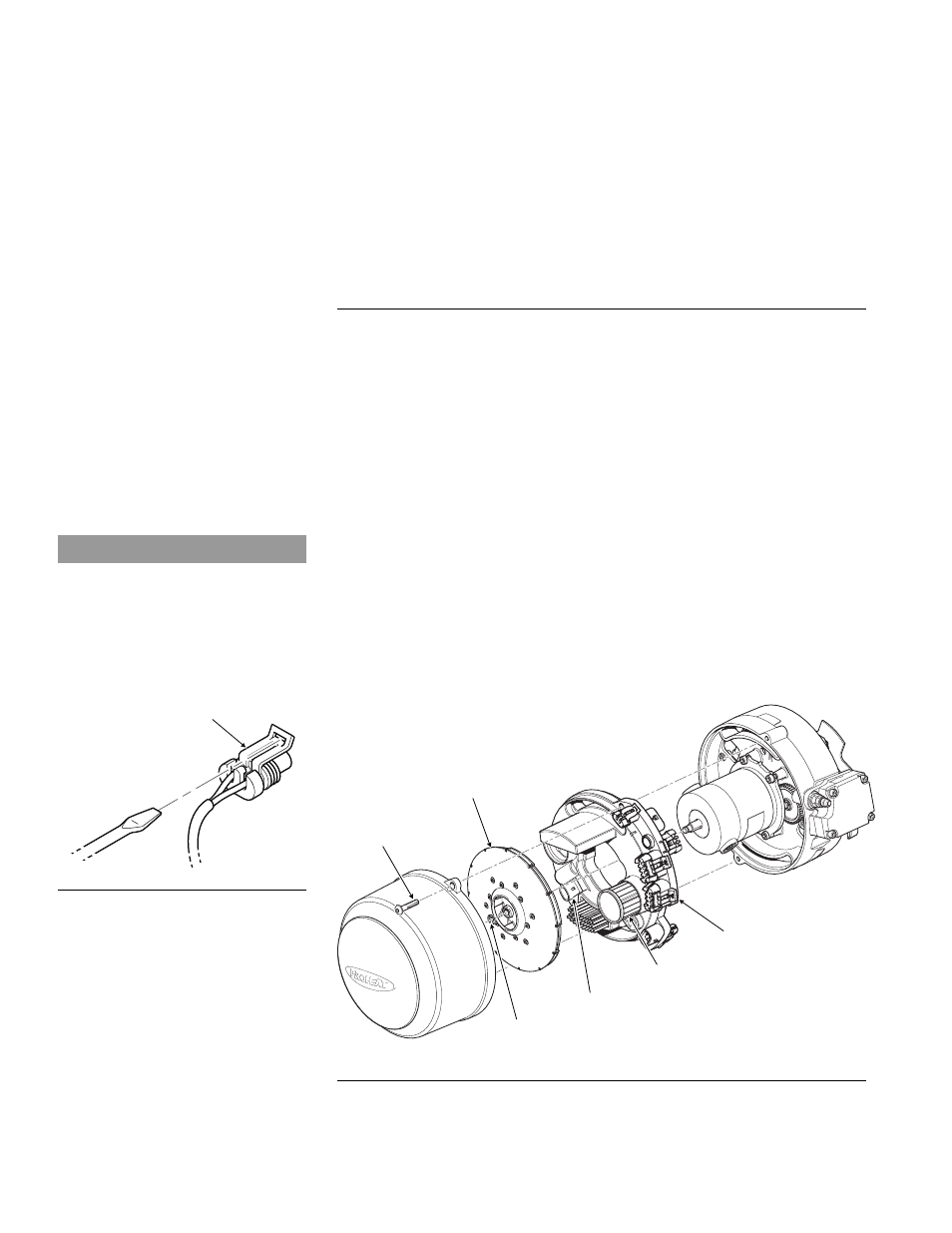
Figure 4-41: G-II PCM Replacement.
BLOWER
BLOWER RETAINING SNAP RING
AIR COMPRESSOR FILTER
G-II PCM
SCREWS (2)
TORQUE = SEE
SECTION 1.3
G-II PCM MOTOR CONNECTION
LOCK
Figure 4-40: Connector Removal.
4-38
PROHEAT M-SERIES G-II PCM SERVICE MANUAL