Installation – Desa Tech S26PTA User Manual
Page 12
www.desatech.com
110361-01E
12
INSTALLATION
Continued
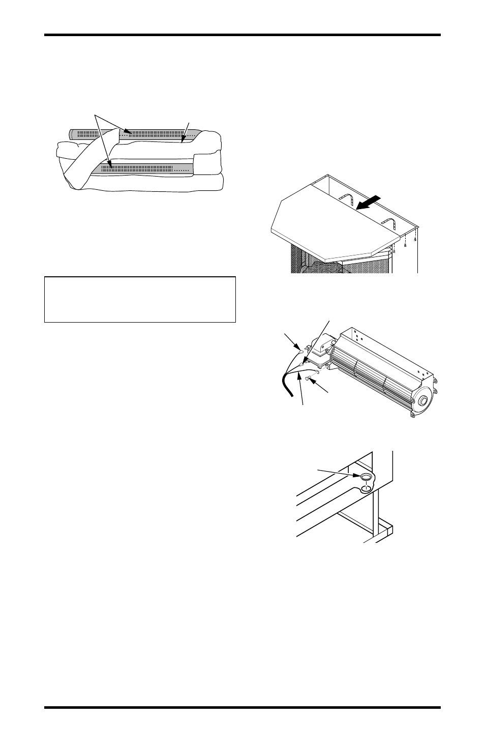
IMPORTANT:
Make sure log does not cover any
burner ports (see Figure 12).
Figure 12 - Installing One-Piece Log set
(Top View)
One Piece
Log Set
Burner Ports
INSTALLING BLOWER ACCESSORY
GA3750
Tools required: Phillips screwdriver
NOTICE: Shut off gas heater dur-
ing the following blower instal-
lation.
1.
Remove top panel of stove by removing three
screws from under top lip on each side of stove
(see Figure 13).
2.
Facing front of stove, carefully slide top panel
forward until it is completely removed from
stove (see Figure 13).
3.
Disconnect power cord wires from blower
motor (if connected) (see Figure 14).
4.
Disconnect green ground wire from blower
housing (if connected) by removing screw
holding wire terminal (see Figure 14).
5.
Install one plastic bushing provided in blower
kit into the 1
1
/
2
" hole in the left rear of fire-
box floor. Access hole through the rectangu-
lar opening in the rear panel (see Figure 15).
6.
Remove the two blower mounting brackets
from the rear panel by removing two screws
each (see Figure 16, page 13).
7.
Attach the two mounting brackets to blower
housing using four screws provided in blower
kit (2 for each bracket) (see Figure 16, page 13).
Tighten screws securely. Place blower assem-
bly temporarily on top of firebox.
8.
Working from the rear of the stove, place en-
tire power cord, including speed control hous-
ing, in lower control compartment.
9.
Route ends of 3-wire power cord up from the
lower control compartment through the plas-
tic bushing, then up to the upper cavity of stove
(see Figure 17, page 13).
10. Attach the terminal ends of the white and black
power cord wires to the terminals on the
blower motor (see Figure 14). Push firmly.
11. Attach the terminal end of the green power
cord wire to the front tab of the blower hous-
ing using screw provided (see Figure 14).
Figure 13 - Removing Stove Top Panel
Figure 14 - Removing Wires from Blower
Figure 15 - Installing Bushing
Screw
Green Ground Wire
White
Powercord
Wire
Black Powercord Wire
Bushing