Cabletron Systems 9F310-02 User Manual
Page 25
4-3
The function of the FDDI receive LEDs are listed in Table 4-4.
The function of the FDDI transmit LEDs are listed in Table 4-2.
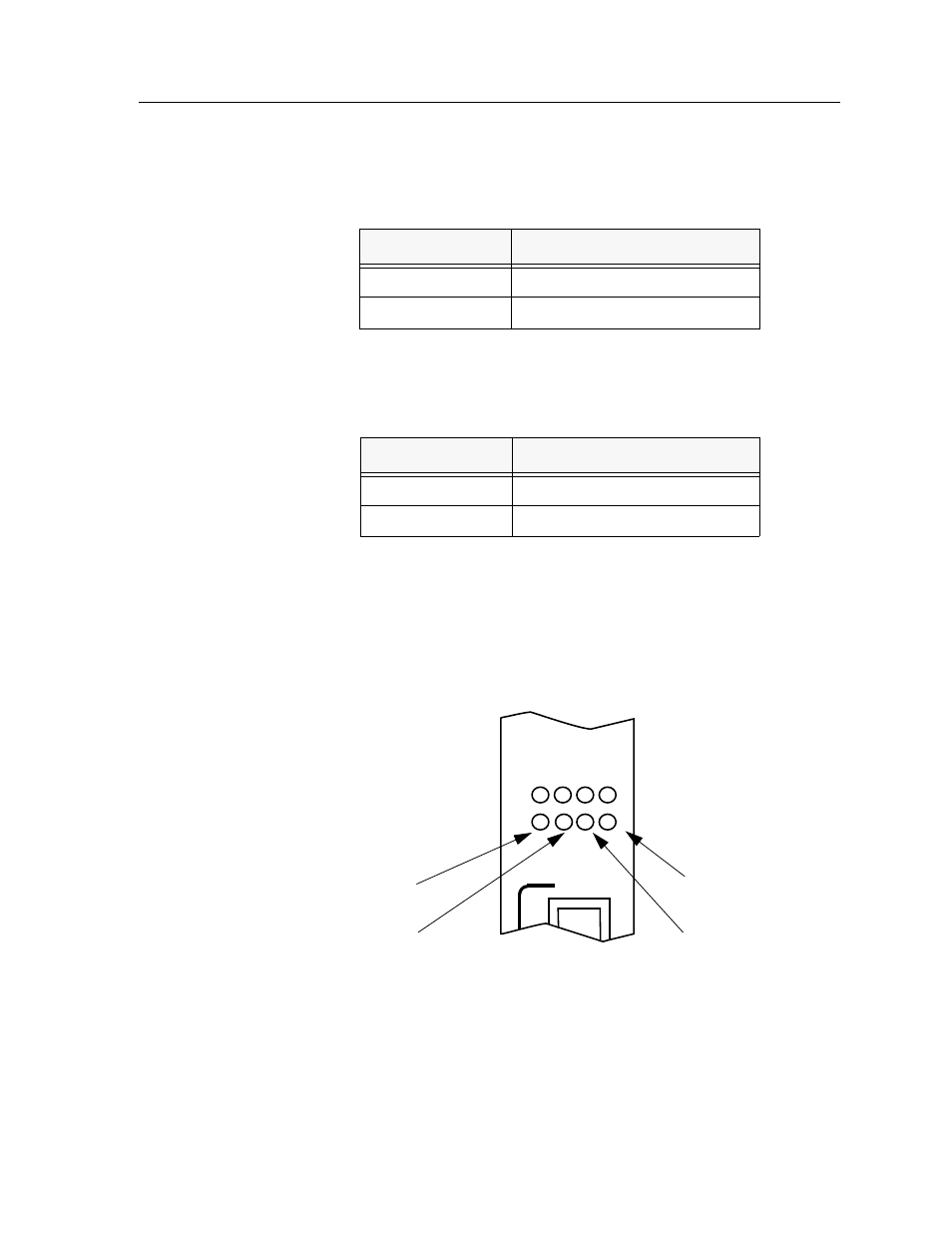
The FDDI status LEDs display the status when bridging to the front panel port
from either FNB ring. The “A” and “B” LEDs indicate the status of the A and B
ports. The “P” and “S” LEDs indicate the status of the primary and secondary
FDDI rings. When bridging between FNB rings, the FDDI status LEDs are not
operational. The FDDI Status LEDs are shown in Figure 4-2.
Figure 4-2. FDDI Status LEDs
Table 4-4. FDDI Receive LEDs
LED Color
State
Yellow (Flashing)
Activity
Off
No Activity
Table 4-5. FDDI Transmit LEDs
LED Color
State
Green (Flashing)
Activity
Off
No Activity
1
2
A
P
B
S
This manual is related to the following products: