Connect a coaxial cable to the out to, Tv (a, Ooking – Philips PR1335B User Manual
Page 2: Ntenna, Able, Onnections
Attention! The text in this document has been recognized automatically. To view the original document, you can use the "Original mode".
H
ooking
U
p
Y
our
TV (A
ntenna
/C
able
C
onnections
)
¡I
I
C
ombination
UHF/VHF
A
ntenna
A
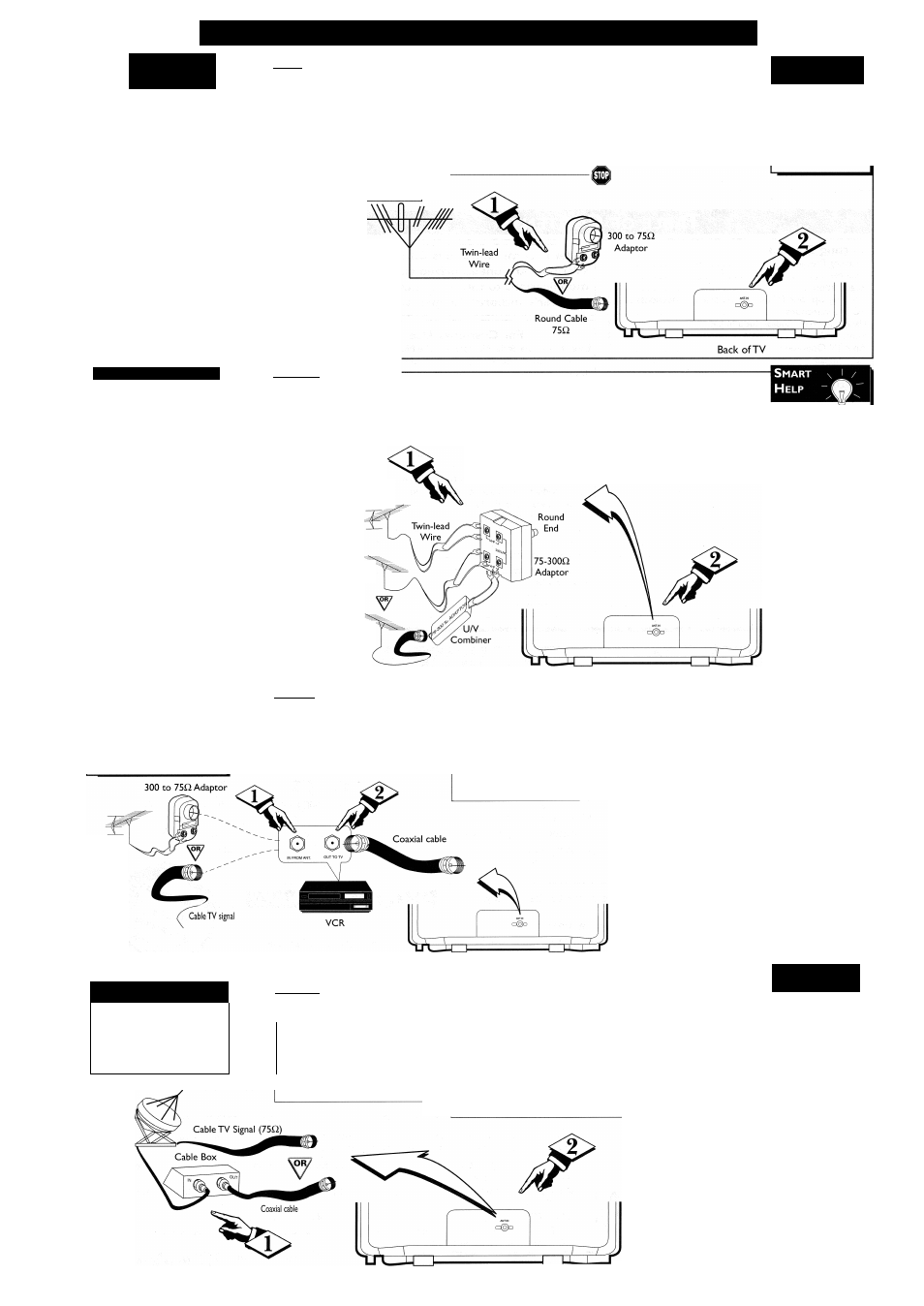
combination antenna
receives normal broadcast
channels (VHF 2-13 and UHF
l4-69).Your connection is easy
since there is only one 75Q.
(ohm) antenna jack on the
back of your TV - and thafs
where the antenna goes.
-(BEGIN)----------------------------------------------
[<}> f your antenna has a
round connector (75Q),
then you're ready to connect it
to the TV
If your antenna has flat
twin-lead wire (300Q), you
first need to attach the antenna
wires to the screws on a 300
to 75Q adaptor.
Combination
VHF/UHF
Antenna
(Outdoor or
Indoor)
Push the round end of
the adaptor (or cable) onto
the ANT(enna) IN jack on
the back of the TV. If the
round end of the adaptor or
cable is threaded, screw it
down tight.
S
mart
\
i
/
H
elp
To set the _
TV to select only
the channel numbers
in your area, see
Auto Install on page
4.
S
eparate
UHF/VHF
Y
OU
may have two separate
antennas. One antenna is for
VHF channels (2-13) and the
other antenna is for UHF chan
nels (14-69).
For homes with separate
UHF/VHF antennas, you will
need an optional combiner
before you can connect the
antennas to the TV.
iBEGIN>-
i
Attach
the
separate
UHF and VHF antennas to
the correct screws on the
combiner.
Push the round end of the
I combiner onto the ANT(enna)
IN jack on the back of the TV.
Outdoor UHF Antenna
(Twin-lead 3000)
Outdoor VHF
Antenna
(Twin-lead 3000)
Outdoor VHF Antenna
(Round cable 750)
To order _
any optional
accessory, contact
your dealer. Or, call
1-800-851-8885 and
refer to the follow
ing part numbers to
order.
• UHF/VHF
Combiner:
4835 466 97016
• 75-3000
Adaptor:
M6I009
• 300-750
Adaptor:
4835 218 27003
Back ofTV
T
'he basic Antenna/Cable to
VCR to TV connection is
shown here. If you have a Cable
Box, refer to the VCR owner's
manual for details.
-CBEGIN3-
i Connect your
Antenna or Cable signal to
the IN FROM ANT(enna)
jack on the VCR.
Connect a coaxial
cable to the OUT TO
TV jack on the VCR
and to the ANT(enna)
IN jack on the TV.
The coaxial cable may be
supplied with the VCR.
Refer to the VCR
owner's manual for other
possible connections and for
operating details.
Outdoor
VHF/UHF
Antenna
Back of TV
C
able
TV
(
^our Cable TV signal may be
1 a single (75Q) cable or a
Cable Box installation. In either
case, the connection to the TV h
very easy.
(BEGIN)-
r<>>
If you do not have a
Cable Box, then you're ready
to connect your Cable TV signal
to the TV.
If you have a Cable Box:
Connect the Cable TV signal to
the IN jack on the Cable Box.
Cable TV
Company
If you do not have a Cable Box, connect the
Cable TV signal directly to the ANT(enna) IN jack on the
TV.
If you have a Cable Box:
Use a coaxial cable to connect the OUT jack of the Cable
Box to the ANT(enna) IN jack on the TV.
NOTE: The coaxial cable might be supplied by the Cable
TV company.
S
mart
\
i
/
H
elp
To select
only the channels on
your Gable system,
see Auto Install
(page 4).
If you use a Cable
Box, set the TV to
the same channel as
the CH 3/4 switch
on the back of the
Cable Box and
select channels at
the Cable Box.
Back of TV
Note to the Cable TV System Installer:
This reminder is provided to call the Cable TV
system installer’s attention to Article 820-40 of
the National Electrical Code, which provides
guidelines for proper grounding - in particular,
specifying that the cable ground shall be con
nected to the grounding system of the building,
as close to the point of cable entry as possible.