Pci interrupt, clock and id selection – Connect Tech CANpro/104-Plus User Manual
Page 8
CANpro/104-Plus Opto User Manual
CTIM-00052 Revision 0.00 4/23/2009
www.connecttech.com
8
800-426-8979 | 519-836-1291
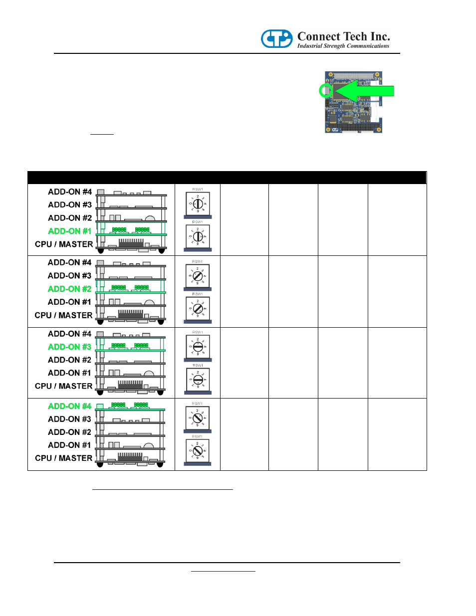
PCI Interrupt, Clock and ID Selection
The following PCI signals, (INTA#, INTB# INTC# INTD#), (CLK0, CLK1,
CLK2, CLK3), (IDSEL0, IDSEL1, IDSEL2, IDSEL3), are selected by using the
Rotary Switch on the CANpro/104-Plus Opto board (RSW1). Selections need to
match the stack location of the CANpro/104-Plus Opto in your PC/104-Plus
stack. See
Rotary Switch Location
Table 1: Rotary Selection
Stack Location
Rotary Setting
PCI INT#
PCI CLK
PCI IDSEL
0 or 4
INTA#
CLK0
IDSEL0
1 or 5
INTB#
CLK1
IDSEL1
2 or 6
INTC#
CLK2
IDSEL2
3 or 7
INTD#
CLK3
IDSEL3
Please vis
to request the full PC/104-Plus specification for
more details on signals.