4 fault indicators, 4 fault indicators –7, Caution – Crown Audio FM1000A User Manual
Page 23: Illustration 3–8 fault indicators, 3–7 operation
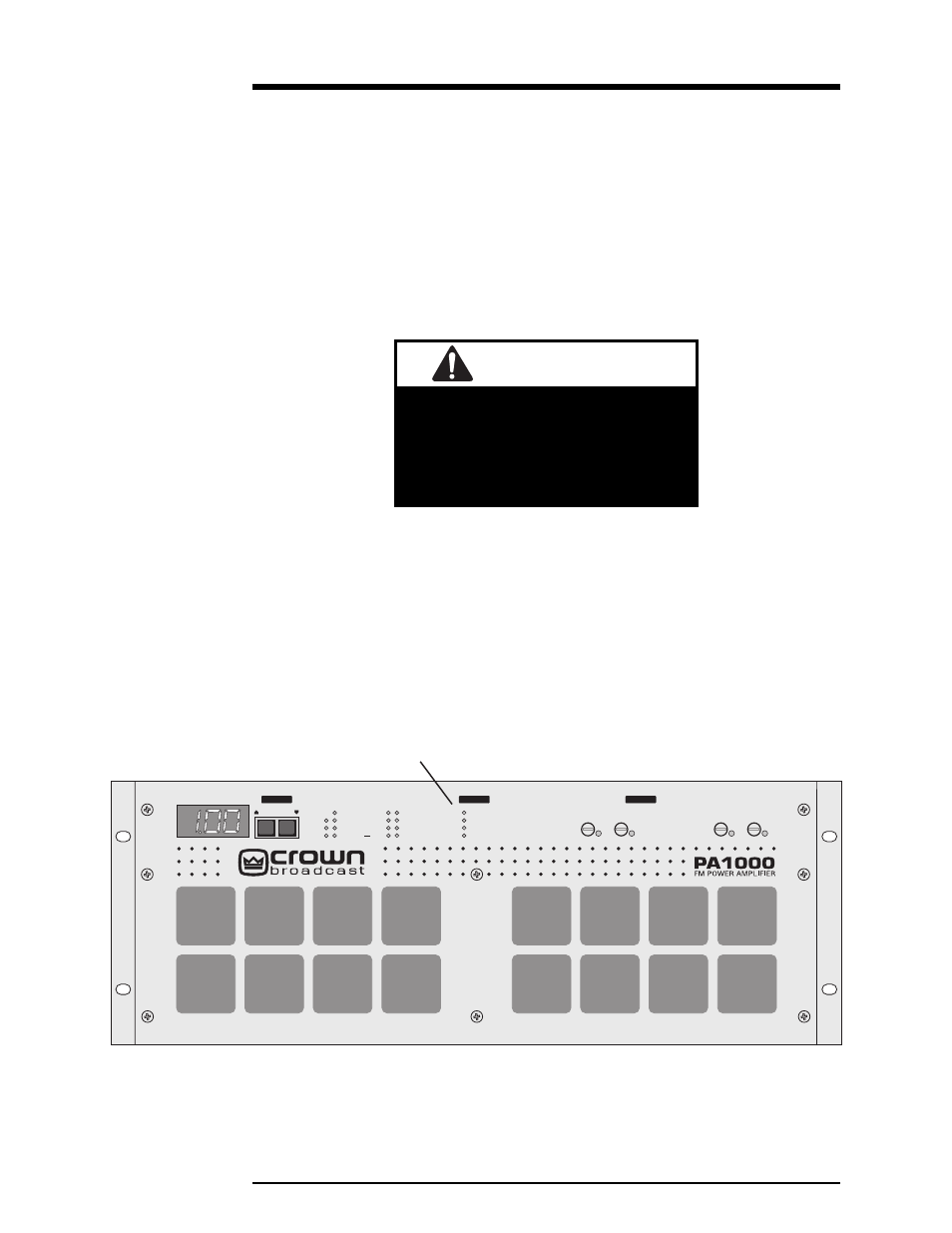
3–7
Operation
3.4 Fault Indicators
Illustration 3–8 Fault Indicators
CAUTION
Possible equipment damage!
Do not exceed 40 watts of input drive.
Damage to the PA1000 will result if
this level is exceeded.
Faults are indicated by illuminated red LED’s when the following occurs:
Antenna—Load SWR exceeds 1.5:1. ALC voltage is reduced to limit the reflected
RF power.
RF Drive—Lack of or insufficient RF drive. If the RF drive fault LED is lit, input
drive must be increased. To achieve full output power, 30 watts of input drive is
required.
PA Temp—PA heatsink temperature is greater than 75°C (power foldback will
begin at this point).
PA DC—Power supply current for the PA (power amplifier) is at the preset limit, or
there is a difference of more than 2.5 amps in current between the individual PAs.
When this indicator is on ALC, the voltage is reduced automatically which holds
the supply current to the preset limit.
Fault
Antenna
RF Drive
PA Temp
PA DC
PA1
PA2
PA3
PA4
PA5
PA6
PA7
PA8
Power Out
PA Temp
PA Voltage
Tot Current
ALC
SWR
In Ref
Metering
PA3
PA4 PA7
PA8
Fuses
®
Fault Indicators