3 digital multimeter, 3 digital multimeter –6 – Crown Audio FM1000A User Manual
Page 22
3–6
FM1000A User’s Manual
3.3 Digital Multimeter
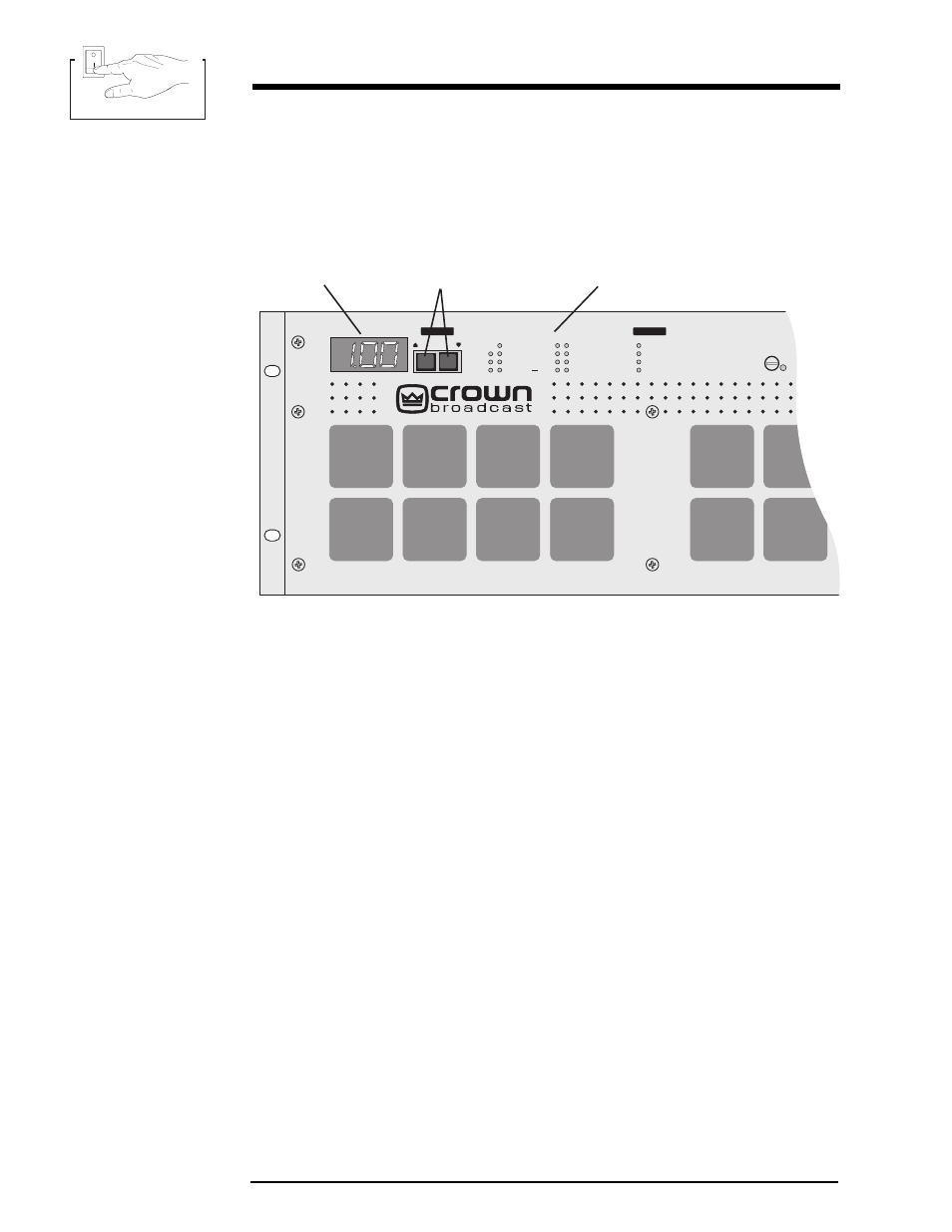
Illustration 3–7 Digital Multimeter
The 3–digit numeric display in the upper left corner of the front panel provides
information on the amplifier’s operation. Use the “up” and “down” push-buttons to
select one of the following parameters as indicated by a green LED.
In Ref—Input reference is a relative voltage level used to determine input RF
power level. This varies between frequency of operation and input power level.
SWR—Direct reading of the antenna Standing-Wave Ratio (the ratio of the actual
load impedance to the desired 50 ohm load impedance).
ALC—Automatic level control is DC gain control bias used to regulate PA supply
voltage. With the PA power supply at full output voltage, ALC will read about 6.0
volts. When the RF output is being regulated by the RF power control circuit, this
voltage will be reduced, typically reading 5.0 to 6.0 volts. The ALC voltage will be
reduced during PA DC overcurrent, SWR, or overtemperature conditions.
Power Out—Actually reads RF voltage squared, so the accuracy can be affected by
SWR. Tolerance of ± 10% is normal. For exact set-up on site, an external power
meter is recommended.
PA Temp—Highest temperature of all individual RF power amplifier heatsinks in
degrees C.
PA Voltage—Supply voltage of the RF power amplifier.
Tot Current—Sum total current of all individual RF power amplifiers in amperes.
PA1–8—Individual RF amplifier current reading in amperes.
Fault
Antenna
RF Drive
PA Temp
PA DC
PA1
PA2
PA3
PA4
PA5
PA6
PA7
PA8
Power Out
PA Temp
PA Voltage
Tot Current
ALC
SWR
In Ref
Metering
PA3
®
Multimeter
Metering Selection Buttons
Metering Indicators