4 hydraulic plumbing: single acting – NORAC UC5-BC-HD03 User Manual
Page 32
29
10.4 Hydraulic Plumbing: Single Acting
From this point on in the installation the booms will be inoperative until the
hydraulics are fully installed.
1. After the NORAC valve is mounted, the hydraulic hoses and fittings can be plumbed. The
plumbing for the hydraulic circuit is shown schematically in Figure 3.
2. Install the 90 degree fittings on hoses HD06 onto the “B” ports on the NORAC valve
block.
3. Route the free ends of the hoses to each of the wing tilt cylinders.
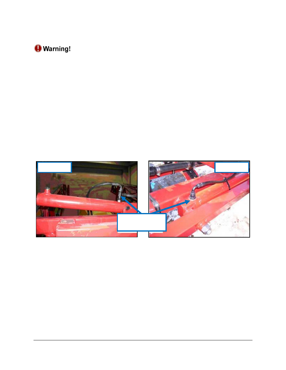
4. Remove the Hardi hoses from the tilt cylinders and replace the restricted BSPP fittings from
the butt ends of the cylinders with the straight through fitting HD04 (Figure 28).
5. Install the 1/4 inch BSP tee union (HD02) onto the fitting on the cylinder and install the
NORAC and Hardi hoses onto the tee union.
Figure 28: Restrictor to be Replaced on the Tilt Cylinders
6. At the Hardi main valve block, remove the hydraulic hoses that run from the butt end of
the tilt cylinders to the valve block.
7. Install the supplied restrictor (HD03) between the hoses and the valve block.
8. Remove the pressure and tank hoses from the Hardi valve block and install the 1/4 inch BSP
tee union (HD02) between the valve block and hoses.
9. Connect hoses HD05 to each of the tee fittings and route to the NORAC valve block.
10. Install the corresponding hose to the pressure and tank port on the NORAC valve block.
Eagle Boom
Force Boom
Replace this
Restrictor