NORAC UC5-BC-FC02 User Manual
Page 25
22
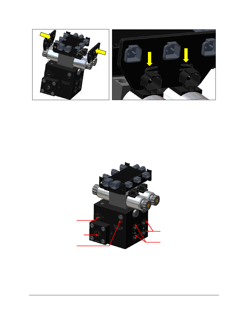
Figure 20: Valve Module Bracket Installation
5. Connect the valve module CANbus to cable C01 from the control module. Route cable
C02 from the other CANbus connector to the input module.
6. With the valve module securely mounted to the valve block, connect the valve cables (C10),
to the valve coils as illustrated in Figure 18 and Figure 21. Insert the 2-pin plugs (P01)
into the unused 2-pin connectors on the valve module.
7. Connect the temperature probe to the valve block using the supplied 3/8” x 1/2” hex bolt.
Figure 21: Valve Module - Valve Coil Connections
Tank Port
Pressure Port
Sense Port
Left Tilt Ports
Right Tilt Ports
See also other documents in the category NORAC Gardening equipment:
- UC4.5-BC-AP3 (35 pages)
- UC4.5-BC-AS1 (22 pages)
- UC4.5-BC-CS1 (34 pages)
- UC4.5-BC-CS2 (35 pages)
- UC4.5-BC-CS3 (36 pages)
- UC4.5-BC-CS5 (42 pages)
- UC4.5-BC-EU1 (42 pages)
- UC4.5-BC-FC1 (29 pages)
- UC4.5-BC-FC2 (32 pages)
- UC4.5-BC-FT1 (32 pages)
- UC4.5-BC-FT3 (33 pages)
- UC4.5-BC-GN1 (38 pages)
- UC4.5-BC-GN2 Part 1 (20 pages)
- UC4.5-BC-GN2 Part 2 (11 pages)
- UC4.5-BC-GN6 (22 pages)
- UC4.5-BC-HD1 (32 pages)
- UC4.5-BC-HD3 Part 1 (36 pages)
- UC4.5-BC-HD3 Part 2 (7 pages)
- UC4.5-BC-HD4 Part 1 (45 pages)
- UC4.5-BC-HD4 Part 2 (7 pages)
- UC4.5-BC-HD5 Part 1 (31 pages)
- UC4.5-BC-HD5 Part 2 (10 pages)
- UC4.5-BC-HD7 (39 pages)
- UC4.5-BC-HD9 (24 pages)
- UC4.5-BC-JD6 (37 pages)
- UC4.5-BC-JD7 (42 pages)
- UC4.5-BC-JD8 (35 pages)
- UC4.5-BC-JD8A (46 pages)
- UC4.5-BC-JD11 (33 pages)
- UC4.5-BC-MC1 (31 pages)
- UC4.5-BC-MC2 (31 pages)
- UC4.5-BC-MS1 (32 pages)
- UC4.5-BC-NT3 (31 pages)
- UC4.5-BC-NT4 (35 pages)
- UC4.5-BC-PS1 (38 pages)
- UC4.5-BC-RA1 (42 pages)
- UC4.5-BC-RA2 (27 pages)
- UC4.5-BC-RG2 (38 pages)
- UC4.5-BC-RG4 (36 pages)
- UC4.5-BC-RG5 (35 pages)
- UC4.5-BC-SC2 (33 pages)
- UC4.5-BC-SC4 (28 pages)
- UC4.5-BC-SM2 (30 pages)
- UC4.5-BC-SS1 (34 pages)
- UC4.5-BC-TA1 (36 pages)