3 hydraulic plumbing – NORAC UC4.5-BC-TA1 User Manual
Page 26
23
8.3 Hydraulic Plumbing
From this point on in the installation the booms will be inoperative until the
hydraulics are fully installed.
Ensure there are no other orifices present in the circuit between the NORAC
valve block and the boom cylinders.
1. After the NORAC valves are mounted, the hydraulic hoses and fittings can be plumbed. The
plumbing for the hydraulic circuit is shown schematically in Figure 3 and Figure 4.
1. Disconnect the existing “raise” lines from the valve block. Connect the “raise” lines to the
“B” ports leading from the NORAC valve block.
2. Install the 6FJCN fittings (F03) onto the disconnected ports of the valve block.
3. Disconnect the accumulators from the tee fittings on the left and right tilt boom cylinders.
Remove the fittings attached to the accumulators.
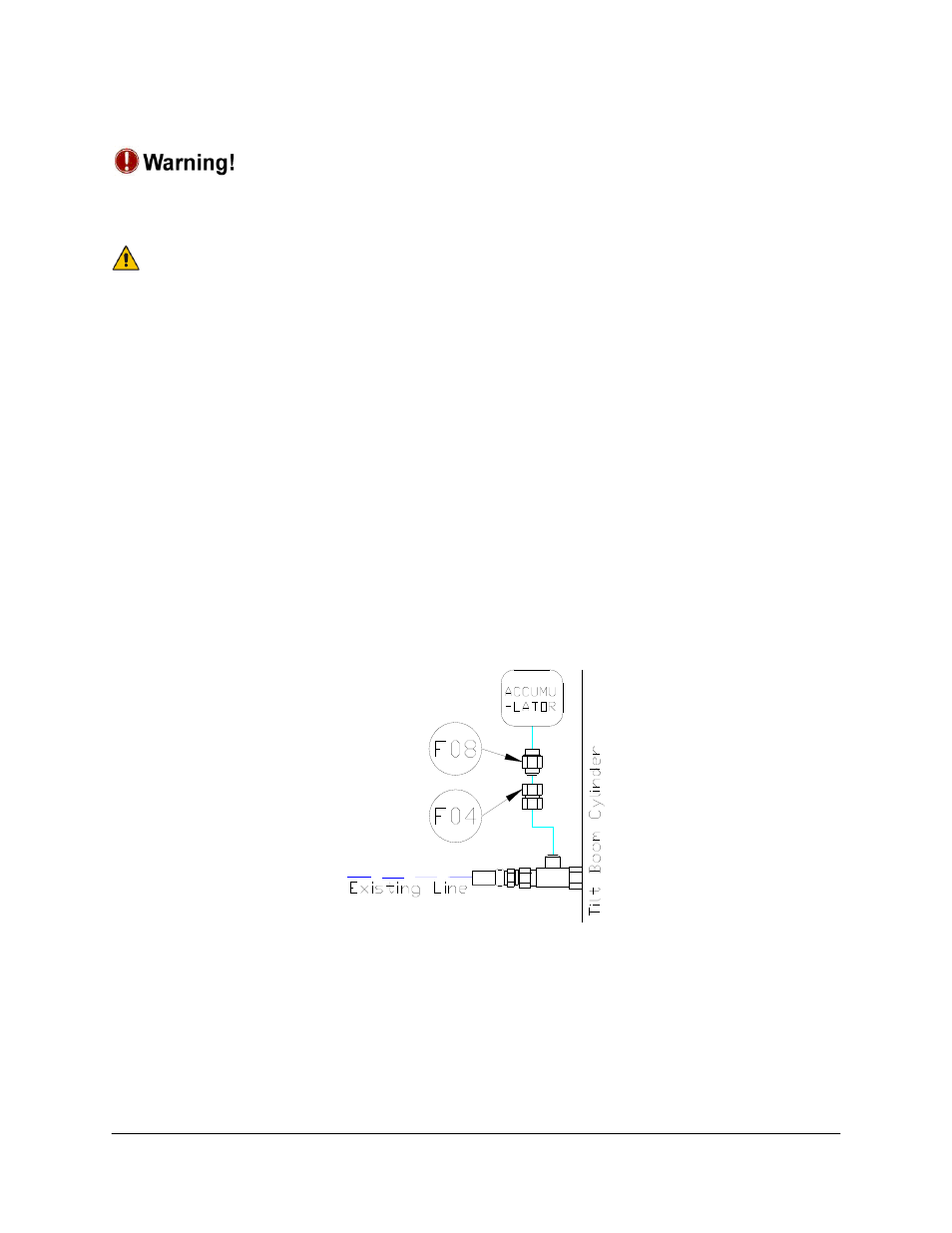
4. Insert the 8MB-8MJ with orifice adapters (F08) and the 8FJX unions between the
accumulators and the tee fittings on the cylinders (F04) (Figure 23).
5. Tee the pressure (H04) and tank (H03) lines for the NORAC block in to the existing lines
from the existing valve block, using the “T” fitting (F02).
Figure 23: Accumulator Fittings
6. Disconnect the tank line from the sprayer valve block and insert a 6FJXR 6MJT tee (F02)
between the hose and the valve block.
7. Connect hose H03 from the free end of the tee (F02) at the tank port on the sprayer valve
block to the tank port on the NORAC valve block.