2 valve block mounting – NORAC UC4.5-BC-TA1 User Manual
Page 25
22
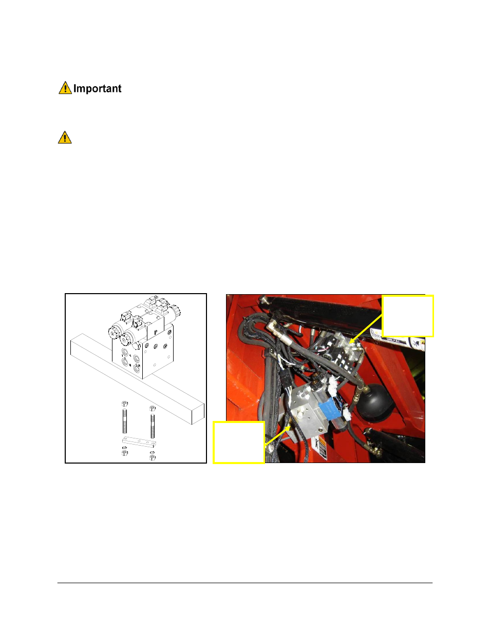
8.2 Valve Block Mounting
Ensure that no hydraulic components will interfere with any sprayer parts or be
pulled tight at any time.
The recommended location for the NORAC valve block is on the rear of the
boom center section on the horizontal cross member, near the existing valve
block.
1. A suitable mounting location for the valve block is illustrated in Figure 22.
2. Insert the threaded rod into the block and use a hex nut to hold the rod. The block holes
are 3/8” NC-1” deep. If bolts are used instead of the threaded rod, ensure the bolts thread
in at least 3/8”.
3. Use the remaining hardware to secure the block to the sprayer.
4. Cut off excess threaded rod, if necessary.
Figure 22: Valve Block Mounting
NORAC
Valve
Block
Existing
Valve
Block
- UC4.5-BC-AP3 (35 pages)
- UC4.5-BC-AS1 (22 pages)
- UC4.5-BC-CS1 (34 pages)
- UC4.5-BC-CS2 (35 pages)
- UC4.5-BC-CS3 (36 pages)
- UC4.5-BC-CS5 (42 pages)
- UC4.5-BC-EU1 (42 pages)
- UC4.5-BC-FC1 (29 pages)
- UC4.5-BC-FC2 (32 pages)
- UC4.5-BC-FT1 (32 pages)
- UC4.5-BC-FT3 (33 pages)
- UC4.5-BC-GN1 (38 pages)
- UC4.5-BC-GN2 Part 1 (20 pages)
- UC4.5-BC-GN2 Part 2 (11 pages)
- UC4.5-BC-GN6 (22 pages)
- UC4.5-BC-HD1 (32 pages)
- UC4.5-BC-HD3 Part 1 (36 pages)
- UC4.5-BC-HD3 Part 2 (7 pages)
- UC4.5-BC-HD4 Part 1 (45 pages)
- UC4.5-BC-HD4 Part 2 (7 pages)
- UC4.5-BC-HD5 Part 1 (31 pages)
- UC4.5-BC-HD5 Part 2 (10 pages)
- UC4.5-BC-HD7 (39 pages)
- UC4.5-BC-HD9 (24 pages)
- UC4.5-BC-JD6 (37 pages)
- UC4.5-BC-JD7 (42 pages)
- UC4.5-BC-JD8 (35 pages)
- UC4.5-BC-JD8A (46 pages)
- UC4.5-BC-JD11 (33 pages)
- UC4.5-BC-MC1 (31 pages)
- UC4.5-BC-MC2 (31 pages)
- UC4.5-BC-MS1 (32 pages)
- UC4.5-BC-NT3 (31 pages)
- UC4.5-BC-NT4 (35 pages)
- UC4.5-BC-PS1 (38 pages)
- UC4.5-BC-RA1 (42 pages)
- UC4.5-BC-RA2 (27 pages)
- UC4.5-BC-RG2 (38 pages)
- UC4.5-BC-RG4 (36 pages)
- UC4.5-BC-RG5 (35 pages)
- UC4.5-BC-SC2 (33 pages)
- UC4.5-BC-SC4 (28 pages)
- UC4.5-BC-SM2 (30 pages)
- UC4.5-BC-SS1 (34 pages)