2 valve block mounting – NORAC UC4.5-BC-SC2 User Manual
Page 23
20
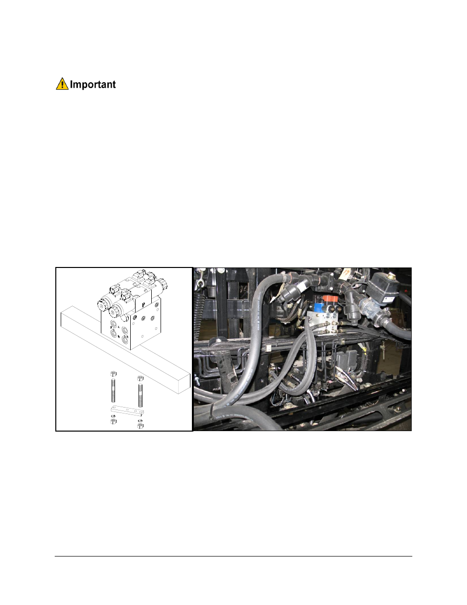
8.2 Valve Block Mounting
Ensure that no hydraulic components will interfere with any sprayer parts or be
pulled tight at any time.
1. The recommended location for the valve is on the rear of the boom main section on the
horizontal cross member, above the Spra-Coupe valve block. Orient the valve block so the
NORAC block pressure and tank lines are on the same side as the Spra-Coupe pressure
and tank lines.
2. Insert the threaded rod into the block and use a hex nut to hold the rod. The block holes
are 3/8” NC-1” deep. If bolts are used instead of the threaded rod, ensure the bolts thread
in at least 3/8”.
3. Use the remaining hardware to secure the block to the sprayer.
4. Cut off excess threaded rod, if necessary.
Figure 20: Valve Block Mounting
- UC4.5-BC-AP3 (35 pages)
- UC4.5-BC-AS1 (22 pages)
- UC4.5-BC-CS1 (34 pages)
- UC4.5-BC-CS2 (35 pages)
- UC4.5-BC-CS3 (36 pages)
- UC4.5-BC-CS5 (42 pages)
- UC4.5-BC-EU1 (42 pages)
- UC4.5-BC-FC1 (29 pages)
- UC4.5-BC-FC2 (32 pages)
- UC4.5-BC-FT1 (32 pages)
- UC4.5-BC-FT3 (33 pages)
- UC4.5-BC-GN1 (38 pages)
- UC4.5-BC-GN2 Part 1 (20 pages)
- UC4.5-BC-GN2 Part 2 (11 pages)
- UC4.5-BC-GN6 (22 pages)
- UC4.5-BC-HD1 (32 pages)
- UC4.5-BC-HD3 Part 1 (36 pages)
- UC4.5-BC-HD3 Part 2 (7 pages)
- UC4.5-BC-HD4 Part 1 (45 pages)
- UC4.5-BC-HD4 Part 2 (7 pages)
- UC4.5-BC-HD5 Part 1 (31 pages)
- UC4.5-BC-HD5 Part 2 (10 pages)
- UC4.5-BC-HD7 (39 pages)
- UC4.5-BC-HD9 (24 pages)
- UC4.5-BC-JD6 (37 pages)
- UC4.5-BC-JD7 (42 pages)
- UC4.5-BC-JD8 (35 pages)
- UC4.5-BC-JD8A (46 pages)
- UC4.5-BC-JD11 (33 pages)
- UC4.5-BC-MC1 (31 pages)
- UC4.5-BC-MC2 (31 pages)
- UC4.5-BC-MS1 (32 pages)
- UC4.5-BC-NT3 (31 pages)
- UC4.5-BC-NT4 (35 pages)
- UC4.5-BC-PS1 (38 pages)
- UC4.5-BC-RA1 (42 pages)
- UC4.5-BC-RA2 (27 pages)
- UC4.5-BC-RG2 (38 pages)
- UC4.5-BC-RG4 (36 pages)
- UC4.5-BC-RG5 (35 pages)
- UC4.5-BC-SC4 (28 pages)
- UC4.5-BC-SM2 (30 pages)
- UC4.5-BC-SS1 (34 pages)
- UC4.5-BC-TA1 (36 pages)