NORAC UC4.5-BC-SC2 User Manual
Page 19
16
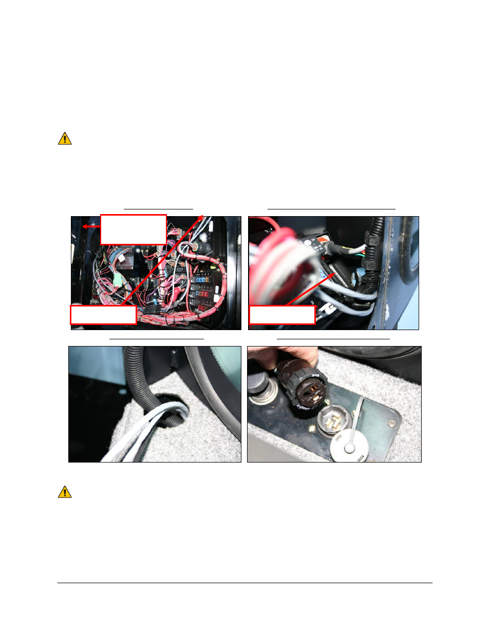
6. On the left side of the electrical panel (Figure 16), there is a knockout. Remove the
knockout and install the grommet (M15). The grommet may fit easier if it is cut radially (ie.
like a lockwasher).
7. Route the Jam Valve Cable (C13) through the grommet. Connect the 2-pin shroud on C13
to the 2-pin tower on C10B.
It may be easier installing the cables first, while installing the grommet (M15)
later.
8. Route C06 through the grommet. Then route the unpinned end of the valve extension
cable (C04) through the grommet as well.
Electrical Panel
BOTTOM (view from panel)
TOP (view from cab)
3-PIN Power Connection
Figure 16: Power Cable Routing (C10)
The valve extension cable (C04) is packaged with one GP end not installed.
This is normal; it helps installations for these sprayer types. Pin this connector
(connector included) as per drawing in Section 10. TAKE EXTRA CARE!
These pins require a special tool to remove them if an error is made!
Access
Hole
Access Hole
Grommet
w/Knockout
Access Hole