NORAC UC4.5-BC-SC2 User Manual
Page 20
17
9. Connect 6-pin shroud on C04 to the 6-pin tower on C10B.
10. Disconnect C10A from C10B at the 4-pin Sense Line connectors (Figure 15).
11. Find the Spra Coupe joystick wiring harness located in the driver’s seat right-hand armrest.
It will have four grey 24-pin square Deutsch connectors. Disconnect these connectors
from each other, carefully noting their “mates”.
Write down the wire colors and which connectors lead up to the joystick
before disconnecting.
12. Connect the four large (24-pin) mating Deutsch connectors on C10A in line with the
disconnected Spra Coupe connectors. The two connectors labeled “JOYSTICK” should be
connected to the Spra Coupe connectors that lead up to the joystick.
Refer to Section 10 for the wire colors to check the connectors’ correctness.
13. Route the 4-pin “Sense Line” shroud on C10B through a hole in the armrest, then through
a hole near the floor (behind and to the right of the driver’s seat), into the electrical panel
(outside).
14. Reconnect the 4-pin shroud on C10B to the mating 4-pin tower on C10A to make it one
piece again.
15. Route C04, C06 and C13 on the underbelly of the sprayer. Fasten with cable ties.
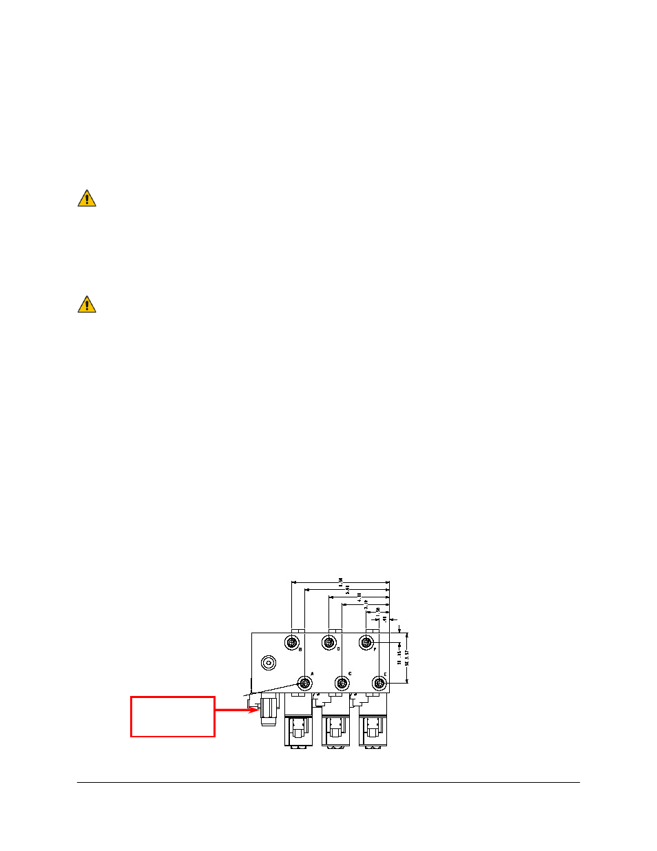
16. Route C13 to the Spra Coupe Jam Valve. It is located in front of the main mast, closest to
the sprayer’s tank and is a 3-way valve bank. Do not confuse this valve block with the 6-
way Spra Coupe block located on the mast itself. The Jam Valve is the leftmost valve when
facing towards the front of the sprayer (Figure 17).
17. Disconnect the Spra Coupe 2-pin connectors attached to the Jam Valve, and insert the 2-
pin Deutsch connector tee on C13 between them.
Figure 17: Spra Coupe Bypass (Jam) Location
Bypass (Jam)
Valve