NORAC UC4.5-BC-JD8A User Manual
Page 25
23
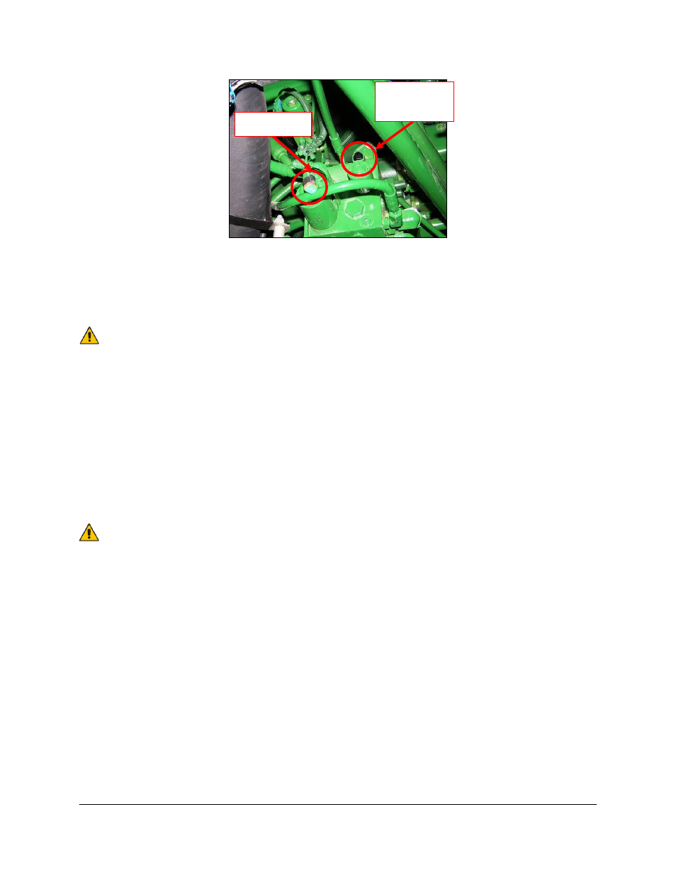
Figure 25: Load Sense Jam Valve Connector
9. Connect the 6-pin shroud (S6) on cable C17 to the 6-pin tower (T6) on C11.
10. Connect the 3-pin tower (T3) on cable C17 to the 3-pin shroud (S3) on C11.
One connector on C17 will remain disconnected. These are used when
installing other UC4.5 options.
11. Install the two 2-pin connectors on the end of cable C17 to the 3
rd
station of the block as
per Figure 26. The connector marked MAIN DOWN goes on the same side of the
block as the hoses.
12. Connect the 3-pin tower on the roll control cable (C70) to the 3-pin shroud (S3) on cable
C17.
13. Install the 2-pin connectors from C70 onto the expansion block with the connector labeled
ROLL CW on the same side of the block as the hoses.
The two free wires on C70 should be trimmed and sealed with heatshrink or
silicone so they do not short together or get tangled in other components.
14. Connect the 6-pin tower on the valve cable (C03) to the 6-pin shroud on C11.
15. Connect the 2-pin connectors on C03 to the NORAC valve block, as shown in Figure 26.
16. The connectors on the valve cable (C03) are marked RIGHT UP, LEFT UP, RIGHT
DOWN and LEFT DOWN. Cables labeled with UP go on the same side as the
hydraulic hoses.
Connector
Location
Connector