NORAC UC4.5-BC-HD1 User Manual
Page 20
17
The valve extension cable (C04) may be packaged with one GP end not
installed. This is normal; it helps installations for other sprayer types. Pin this
connector on (connector included) as per drawing in Section 10. TAKE
EXTRA CARE! These pins require a special tool to remove them if an error is
made.
6. Route C04 and C06 from the hitch to the rear of the sprayer to the area where the
NORAC hydraulic valves are located.
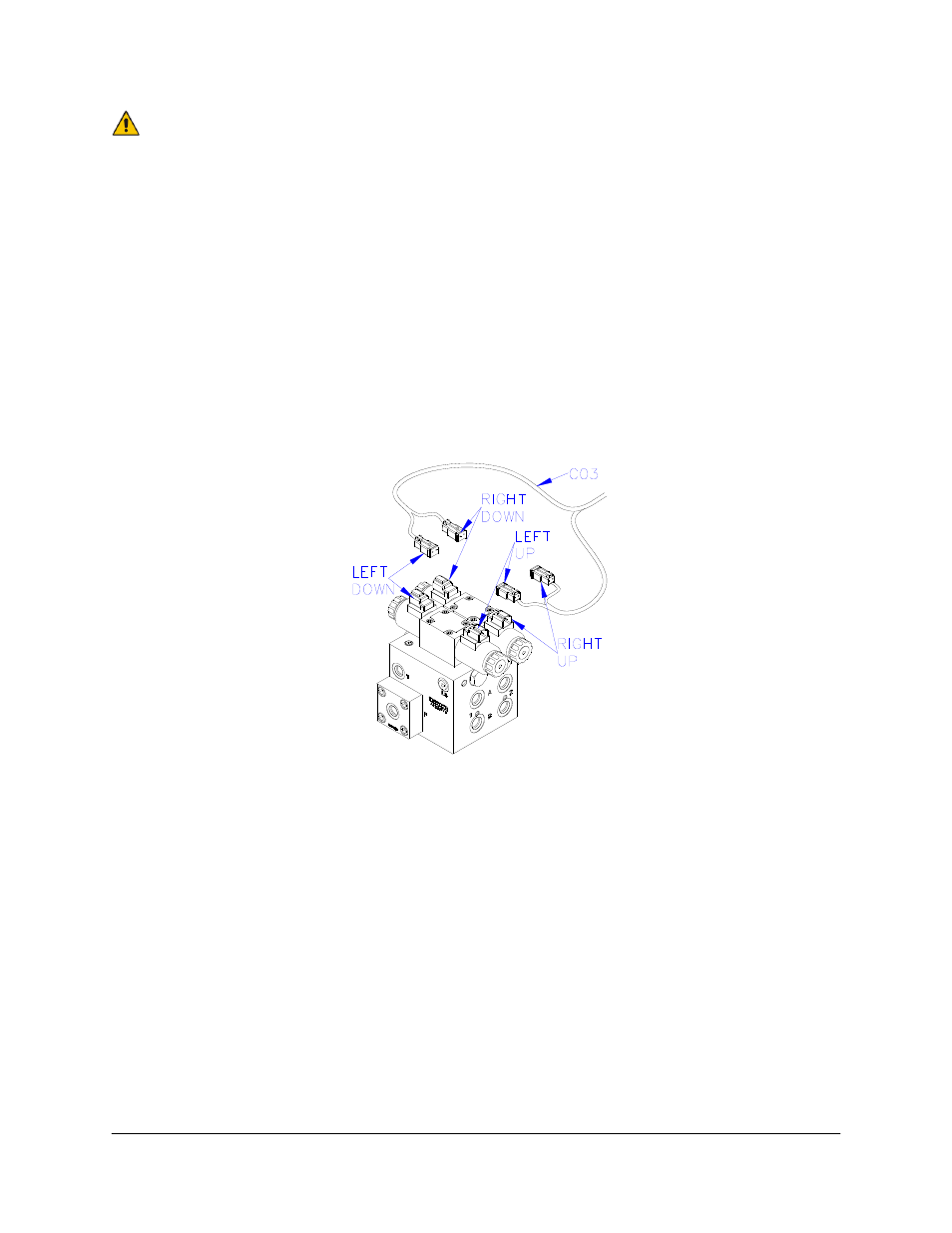
7. Connect the 6-pin tower on C03 to C04. Connect the 2-pin connectors on C03 to the
NORAC valve block, as shown in Figure 16.
8. The connectors on the valve cable (C03) are marked RIGHT UP, LEFT UP, RIGHT
DOWN and LEFT DOWN. Cables labeled with UP go on the same side as the
hydraulic hoses.
Figure 16: Valve Cable Connections
9. Fasten the 8-way coupler to the boom with cable ties. Connect C06 to the 8-way coupler.
10. Connect both roll sensors to the 8-way coupler.
11. Connect two cables (C05) to the 8-way coupler and route along the booms to the wing
sensors. Follow existing cables and hoses to be sure the cable will not be pinched or
stretched.
12. At the sensor brackets, attach a 2-way coupler with terminator (E20) to the sprayer boom.
The 2-way coupler with terminator is the white two way coupler. Plug the sensor and the
CANbus cable into the 2-way coupler.