Crown Audio MT-1200 User Manual
Page 2
Crown International
1718 W. Mishawaka Rd.
Elkhart, IN 46517-9439
TEL: 574-294-8200
FAX: 574-294-8FAX
www.crownaudio.com
Specifi cations subject to change without prior notice. Latest
information available at www.crownaudio.com.
Grounded Bridge is a trademark and Crown, Crown Audio,
ODEP and Micro-Tech are registered trademarks of Crown
International. Other trademarks are the property of their
respective owners. Printed in U.S.A.
© 2005 Crown Audio
®
, Inc.
7/05 136733-1B
Crown’s Three-Year, No-Fault, Fully Transferable Warranty
Crown offers a Three-Year, No-Fault, Fully Transferable Warranty for every new Crown ampli-
fi er—an unsurpassed industry standard. With this unprecedented No-Fault protection, your new
Crown amplifi er is warranted to meet or exceed original specifi cations for the fi rst three years of
ownership. During this time, if your amplifi er fails, or does not perform to original specifi cations,
it will be repaired or replaced at our expense. About the only things not covered by this warranty
are those losses normally covered by insurance and those caused by intentional abuse. And the
coverage is transferable, should you sell your amplifi er.
See your authorized Crown dealer for full warranty disclosure and details. For customers outside
of the USA, please contact your authorized Crown distributor for warranty information or call
574-294-8200.
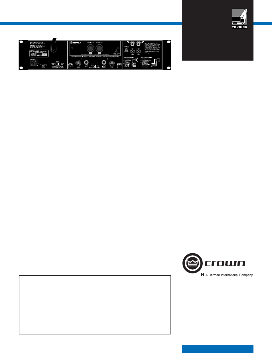
Controls and Connectors
Level: A back panel rotary potentiometer for
each channel used to control the output level.
Power: A front panel rocker switch used to turn
the amplifi er on and off.
Stereo/Mono: A three-position back panel
switch used to select Stereo, Bridge-Mono or
Parallel-Mono mode.
Sensitivity: A three-position switch inside the
back cover plate used to select the input sensi-
tivity for both channels: 0.775 volt or 1.4 volts
for standard 1 kHz power into 8 ohms, or 26
dB gain.
Ground Lift: A two-position back-panel switch
used to isolate the phone jack input grounds
from the AC ground.
Reset: A back-panel pushbutton switch (one
per channel) that resets the circuit breaker.
Indicators
(all located on front panel)
Enable: This amber indicator shows the on/off
status of the low-voltage power supply and
cooling fan.
ODEP: Each channel has an amber front panel
indicator that shows thermal-dynamic energy
reserve. Normally, each ODEP indicator is lit to
show available reserve energy. The indicator
will dim proportionally as the energy reserve
for its channel decreases. In the rare event
that a channel has no reserve, its indicator
will turn off and the ODEP circuitry will limit
the channel’s output drive. They remain off
if the power is turned off, disconnected, or if
the low-voltage power supply fuse blows. A
channel’s ODEP indicator will also remain off if
its high-voltage supply fuse blows (or breaker
opens) or if transformer thermal protection is
activated.
Input/Output
Input Connector: Two balanced 1/4-inch (6.35-
mm) phone jacks in parallel with two XLR
connectors.
Input Impedance: Nominally 20 k ohms, bal-
anced. Nominally 10 k ohms, unbalanced.
Input Sensitivity: Settings include 0.775 volt
and 1.4 volts for standard 1 kHz power, or
26 dB gain.
Output Connectors: Two sets of color-coded
binding posts for banana plugs, spade lugs
or bare wire (European models do not accept
banana plugs).
Output Impedance: Less than 10 milliohms in
series with less than 2 microhenries.
DC Output Offset: (Shorted input) ±10 mil-
livolts.
Output Signal:
Stereo: Unbalanced, two-channel.
Bridge-Mono: Balanced, single-channel.
Channel
1 controls are active; Channel 2
should be turned down.
Parallel-Mono: Unbalanced, single-channel.
Channel 1 controls are active; Channel 2 is
bypassed.
Protection
The Micro-Tech Series amplifi er is protected
against shorted, open or mismatched loads;
overloaded power supplies; excessive tem-
perature, chain destruction phenomena, input
overload damage and high-frequency blowups.
It also protects loudspeakers from input/output
DC and turn-on/turn-off transients.
If unreasonable operating conditions occur,
the patented ODEP circuitry will proportionally
limit the drive level to protect the output stages,
particularly in the case of elevated temperature.
Transformer overheating will result in a tempo-
rary shutdown of the affected channel; when
it has cooled to a safe temperature, the trans-
former will automatically reset itself. Controlled
slew rate voltage amplifi ers prevent RF burn-
outs, and input overload protection is provided
by the input current limit.
Turn On: The four-second turn-on delay pre-
vents dangerous turn-on transients. Turn-on
occurs at zero crossing of the AC waveform, so
power sequencers are rarely needed with mul-
tiple units. Note: To change the turn-on delay
time, contact Crown’s Technical Support Group.
Construction
Steel chassis with durable black fi nish, front
panel Lexan overlay and specially designed
“fl ow-through” ventilation from front to side
panels.
Cooling: Internal heat sinks with forced-air
cooling for rapid, uniform heat dissipation.
Dimensions: EIA Standard 19-inch
(48.3-cm) rack mount width (EIA RS-310-B),
3.5 inches (8.9-cm) high and 16 inches (40.6-
cm) deep behind front mounting surface.
Weight:
Micro-Tech 600: 36 lb, 4 oz (16.5 kg) net.
41, lb 2 oz (18.7 kg) shipping.
Micro-Tech 1200: 41 lb, 1 oz (18.6 kg) net.
45, lb 3 oz (20.5 kg) shipping.
Micro-Tech 2400: 46 lb, 14 oz (21.3 kg) net.
55lb, 12 oz (25.3 kg) shipping.
MT-600
MT-1200
MT-2400
The MT-600 is shown. The MT-2400 is the same but has two reset switches near the power cord.