Specific safety rules functional description, Assembly warning, Specifications symbology – Milwaukee Tool 2311-21 User Manual
Page 4
4
specific safeTy rules
funcTional descripTion
Federal
Communications
Commission
Cat. No.
2311-20
Volts
12 DC
•
Maintain labels and nameplates. These carry
important information. If unreadable or missing,
contact a MILWAUKEE service facility for a free
replacement.
Memory Card
SD
Interface Cable
USB A/USB Mini B
Direct Current
To prevent electric shock, do not allow
product to contact live electrical parts
Federal Communications Commission
User must read operator’s manual
Wear eye protection
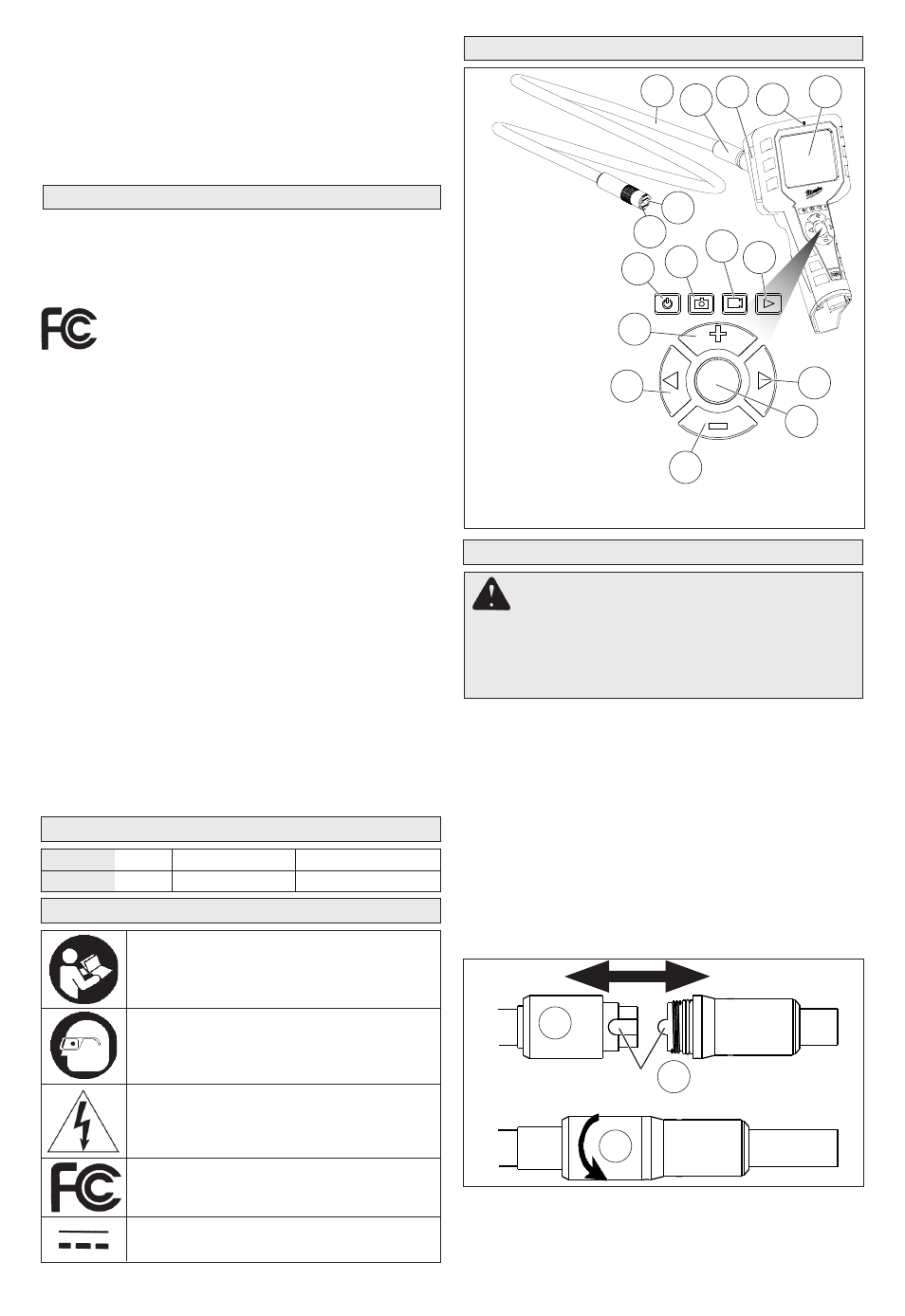
1. Camera
2. Camera LED
3. Cable
4. Socket sleeve
5. Memory card
slot/Interface port
6. Microphone
7. LCD
8. Power button
9. Picture Mode
10. Movie Mode
11. Playback Mode
12. Increase/Up button
13. Left Arrow button
14. Decrease/Down button
15. Select button
16. Right Arrow button
10
9
16
11
12
13
15
4 5
3
6
7
1
2
8
14
WARNING: This is a
class A product. In a
domestic environment
this product may cause radio interference in which
case the user may be required to take adequate
measures.
This equipment has been tested and found to
comply with the limits for a Class A digital device,
pursuant to Part 15 of the FCC Rules. These limits
are designed to provide reasonable protection
against harmful interference when the equipment
is operated in a commercial environment. This
equipment generates, uses, and can radiate radio
frequency energy and, if not installed and used in
accordance with the instruction manual, may cause
harmful interference to radio communications.
Operation of this equipment in a residential area is
likely to cause harmful interference in which case
the user will be required to correct the interference
at his own expense.
This device complies with Part 15 of the FCC Rules.
Operation is subject to the following two conditions:
(1) this device may not cause harmful interfer-
ence, and
(2) this device must accept any interference re-
ceived, including interference that may cause
undesired operation.
assembly
Warning
Recharge only with the
charger specified for the battery. For specific
charging instructions, read the operator’s
manual supplied with your charger and
battery.
Inserting/Removing the Battery
To
remove the battery, push in the release buttons
and pull the battery pack away from the tool.
To
insert the battery, slide the pack into the body
of the tool. Make sure it latches securely into place.
Connecting the Cable
1. Slide back the socket sleeve.
2. Line up the tab on the cable with the detent on
the socket.
3. Press the socket and cable together and slide the
sleeve over the connection. Tighten the sleeve
securely.
Fig. 1
1
2
3
Detent/Tab
specificaTions
symbology
terminal to another. Shorting the battery terminals
together may cause burns or a fire.
• Under abusive conditions, liquid may be eject-
ed from the battery; avoid contact. If contact
accidentally occurs, flush with water. If liquid
contacts eyes, additionally seek medical help.
Liquid ejected from the battery may cause irritation
or burns.