Milwaukee Tool 6394 User Manual
Page 3
4
5
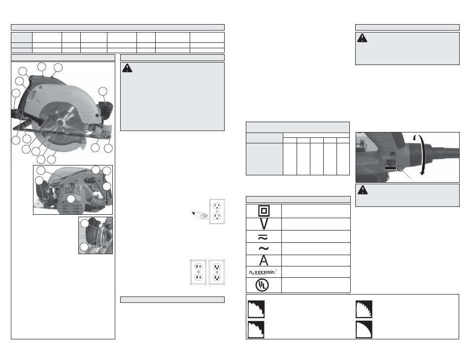
FUNCTIONAL DESCRIPTION
5
4
Cat. No. 6394
ASSEMBLY
Removing and Replacing Positive-Lok
®
Cords
(Cat. No. 6394)
MILWAUKEE’S exclusive Positive-Lok
®
Cords
provide instant fi eld replacement or substitution.
The Positive-Lok
®
feature secures the cord fi rmly
to the tool.
1. To remove the Positive-Lok
®
Cord, push the cord
release button in the direction shown and turn
the cord nut 1/4 turn to the left. Pull the cord out.
2. To replace the Positive-Lok
®
Cord, align the
connector keyways and push the connector in
as far as it will go. Turn the cord nut 1/4 turn to
the right to lock. The cord release button will click
back into place.
Cord release button
Fig. 1
2
1
2
1
WARNING
To reduce the risk of injury,
always unplug tool before attaching or remov-
ing accessories or making adjustments. Use
only specifi cally recommended accessories.
Others may be hazardous.
Fig. B Fig. C
Fig. A
GROUNDING
WARNING
Improperly connecting the
grounding wire can result in the risk of elec-
tric shock. Check with a qualifi ed electrician
if you are in doubt as to whether the outlet is
properly grounded. Do not modify the plug
provided with the tool. Never remove the
grounding prong from the plug. Do not use
the tool if the cord or plug is damaged. If
damaged, have it repaired by a MILWAUKEE
service facility before use. If the plug will not
fi t the outlet, have a proper outlet installed by
a qualifi ed electrician.
Grounded Tools: Tools with Three Prong Plugs
Tools marked “Grounding Required” have a three
wire cord and three prong grounding plug. The
plug must be connected to a properly grounded
outlet (See Figure A). If the tool should electrically
malfunction or break down, grounding provides a
low resistance path to carry electricity away from
the user, reducing the risk of electric shock.
The grounding prong in the plug is connected
through the green wire inside the cord to the
grounding system in the tool. The green wire in the
cord must be the only wire connected to the tool's
grounding system and must never be attached to
an electrically “live” terminal.
Your tool must be plugged into
an appropriate outlet, properly
installed and grounded in accord-
ance with all codes and ordinances.
The plug and outlet should look like
those in Figure A.
Double Insulated Tools:
Tools with Two Prong Plugs
Tools marked “Double Insulated” do not require
grounding. They have a special double insula-
tion system which satisfi es OSHA requirements
and complies with the applicable standards of
Underwriters Laboratories, Inc.,
the Canadian Standard Asso-
ciation and the National Elec-
trical Code. Double Insulated
tools may be used in either of
the 120 volt outlets shown in
Figures B and C.
EXTENSION CORDS
shown to determine the required minimum wire size.
The smaller the gauge number of the wire, the
greater the capacity of the cord. For example, a 14
gauge cord can carry a higher current than a 16
gauge cord. When using more than one extension
cord to make up the total length, be sure each cord
contains at least the minimum wire size required.
If you are using one extension cord for more than
one tool, add the nameplate amperes and use the
sum to determine the required minimum wire size.
Guidelines for Using Extension Cords
• If you are using an extension cord outdoors, be sure
it is marked with the suffi x “W-A” (“W” in Canada)
to indicate that it is acceptable for outdoor use.
• Be sure your extension cord is properly wired
and in good electrical condition. Always replace a
damaged extension cord or have it repaired by a
qualifi ed person before using it.
• Protect your extension cords from sharp objects,
excessive heat and damp or wet areas.
READ AND SAVE ALL
INSTRUCTIONS FOR FUTURE USE.
* Based on limiting the line voltage drop to fi ve volts at
150% of the rated amperes.
SYMBOLOGY
SPECIFICATIONS
Cat. No.
Volts
Amps
No Load
RPM
Blade Size
Arbor
Depth of Cut
at 90°
Depth of Cut
at 45°
6390-20
120 AC/DC
15
6300
7-1/4"
5/8"
0 to 2-15/32"
0 to 1-13/16"
6394
120 AC Only
15
6300
7-1/4"
5/8"
0 to 2-15/32"
0 to 1-13/16"
19
18
17
15
20
14
13
12
1
21
22
2
3
16
1. Tilt-Lok
™
handle
2. Handle lever release button
3. Handle release lever
4. Bevel scale
5. Bevel pointer
6. Bevel adjusting lever
7. Spindle lock button
8. Depth setting gauge (not shown)
9. Trigger
10. Cord release button
11. Depth adjusting lever
12. Front handle
13. Sight line
14. Rip fence slot
15. Lower guard
16. Blade fl ange
17. Blade bolt
18. Blade
19. Shoe
20. Lower guard lever
21. Upper guard
22. Positive-Lok
®
cord (Cat. No. 6394 only)
7
11
9
6
10
8
Selecting Blade
Select a blade appropriate for your application.
Refer to the “Accessories” section for a list of blades
to be used for the proper applications of this tool.
Always use sharp blades. Dull blades tend to
overload the tool and increase the chance of KICK-
BACK. Only use thin kerf blades with a maximum
safe operating speed greater than the no load RPM
marked on the tool's nameplate. Read the blade
manufacturer's instructions before use. Do not use
any type of abrasive cut-off wheel or dry diamond
cutting blades. Use the correct blade type for your
application. Using the wrong blade may result in
reduced performance or damage to the blade. Do
not use blades that are cracked or have broken
teeth. Do not sharpen ferrous metal cutting blades;
see the blade manufacturer's recommendations
regarding sharpening.
WARNING
Only use accessories with
maximum speed rating at least as high as
nameplate RPM of tool.
Fig. 2
Rip & Crosscut
A multi-purpose blade for ripping, cross cut-
ting and mitering in hardwoods, softwoods,
plywood and composition materials.
Framing-Rip
Designed for fast and accurate ripping along
the grain in hard-or softwoods where a
smooth cross cut is not necessary.
Recommended Minimum Wire Gauge
For Extension Cords*
Nameplate Amps
Extension Cord Length
25'
50'
75'
100'
150'
0 - 2.0
2.1 - 3.4
3.5 - 5.0
5.1 - 7.0
7.1 - 12.0
12.1 - 16.0
16.1 - 20.0
18
18
18
18
16
14
12
18
18
18
16
14
12
10
18
18
16
14
12
10
--
18
16
14
12
10
--
--
16
14
12
12
--
--
--
Double Insulated
Volts
Alternating Current/
Direct Current
Alternating Current
Amps
No Load Revolutions per
Minute (RPM)
C
US
Underwriters Laboratories, Inc.
United States and Canada
Grounded tools require a three wire extension cord.
Double insulated tools can use either a two or three wire
extension cord. As the distance from the supply outlet
increases, you must use a heavier gauge extension
cord. Using extension cords with inadequately sized
wire causes a serious drop in voltage, resulting in loss
of power and possible tool damage. Refer to the table
Plywood-Veneer
Recommended for cutting plywood, com-
position materials and all types of wood
where a slightly smoother fi nish is needed.
Finish & Trim
Especially designed for cross cutting and
mitering in materials where a very smooth
cut is necessary. Also cuts aluminum.