Microtel Series 200 User Manual
Page 11
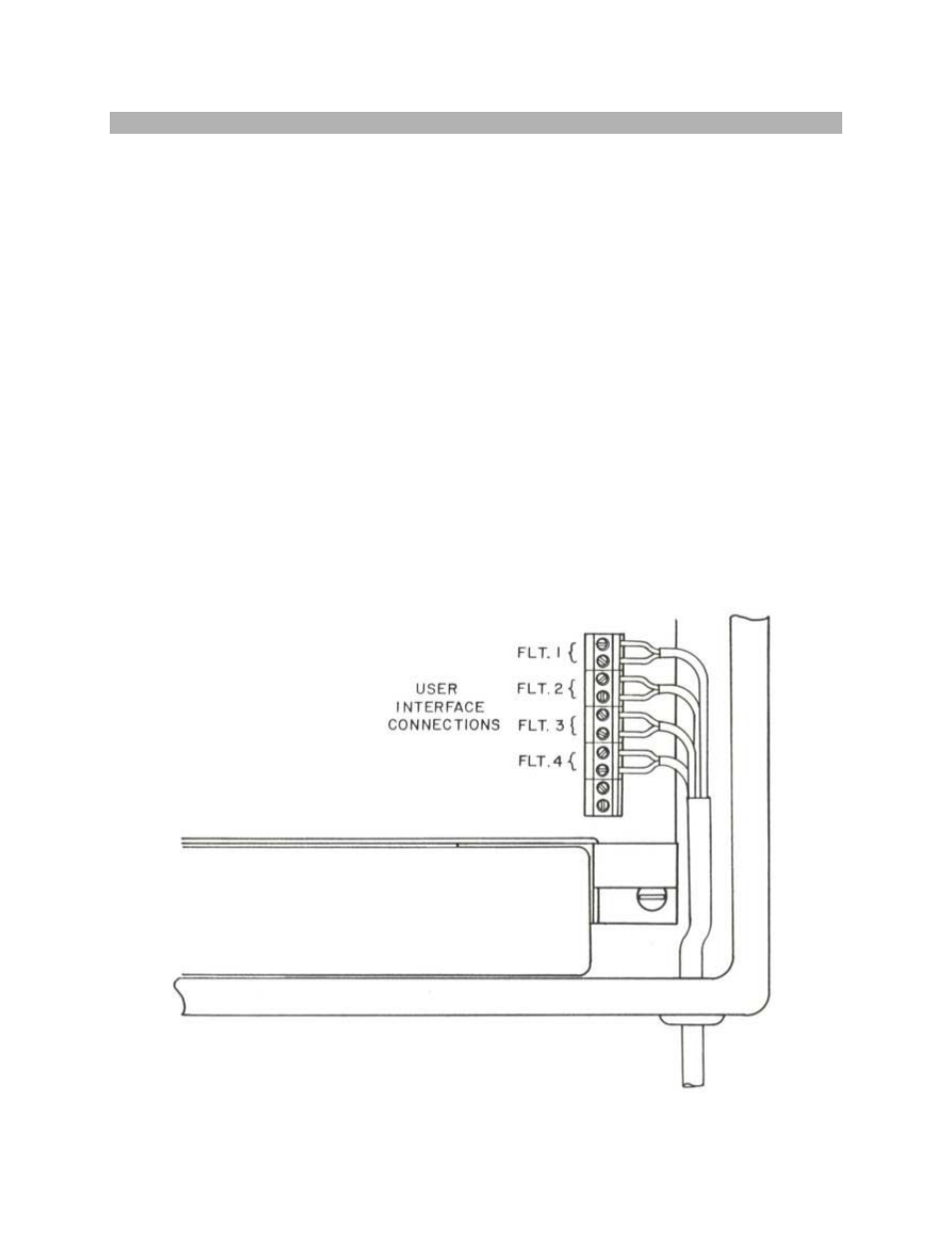
G. FAULT MONITORING INTERFACE CONNECTIONS
The MCS system is designed to accept up to four channels of dry (unpowered),
normally open or normally closed signal lines. The system provides a small,
pulsed sampling current to determine if the contact is open or closed. Leads
from normally open or normally closed switches may be routed through the
conduit port at the lower right side of the system. Connect each wire pair to its
appropriate channel input terminal pair on the Fault Input Terminal Strip.
Shielded, twisted pair, #20 or #22 wire (Belden 8205 or equivalent) is
recommended. If shielded cable is used, ground the shield at the sensor and
leave the shield floating (unconnected) at the MCS system.
Each channel may be configured to be either normally open or normally closed.
A channel should be normally open if the "no fault" (Green) condition is that
condition which consists of an open circuit on that channel's wire pair. A
channel is normally closed if the "no fault" (Green) condition is that condition
which consists of a closed circuit on that channel's wire pair.
The programming section of this manual will provide details on how to program
the Mode (normally open or normally closed) of each channel as well as setting
the Fault Delay time for each channel.
Any unused channel should be left unconnected and programmed to a normally
open mode.
.
7