Make Noise modDemix User Manual
Page 4
1
2
5
4
7
6
8
10
11
12
3
9
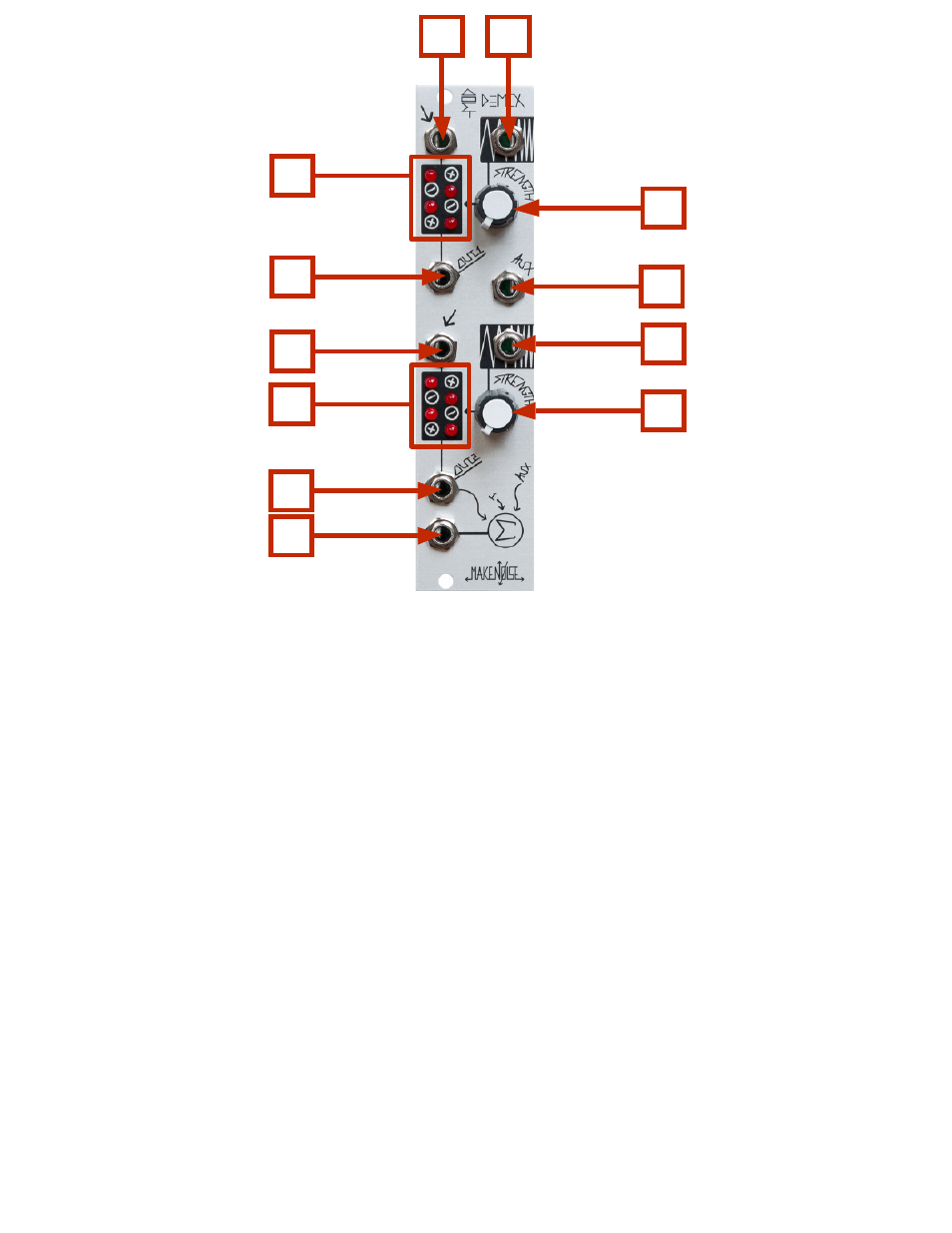
modDemix Panel Controls
1. Signal 1 IN: signal to be processed.
2. Carrier/ CV 1 IN: determines amplitude & phase of Signal 1 IN.
3. Channel 1 LEDs: LED indication of signal activity in four quadrants. Vertical position represents
amplitude and phase of input signal; horizontal position represents amplitude and phase
of carrier/CV input signal.
4. Carrier/ CV 1 Strength: attenuator for Carrier/ CV IN: Normalized to +5V so that with nothing patched
the associated attenuator operates as a unipolar manual control for the parameter.
Range 0V-5V.
5. Signal 1 OUT.
6. AUXiliary INput to Summing stage: An AUXiliary IN allows for the chaining of multiple
modDemix (or Optomix) units to create larger mixes.
7. Signal 2 IN: signal to be processed. Normalled to Signal 1 OUT.
8. Carrier/ CV 2 IN: determines amplitude & phase of Signal 2 IN.
9. Channel 2 LEDs. LED indication of signal activity in four quadrants. Vertical position represents
amplitude and phase of input signal; horizontal position represents amplitude and phase
of carrier/CV input signal.
10. Carrier/ CV 2 Strength: attenuator for Carrier/ CV IN. Normalized to +5V so that with nothing patched,
the associated attenuator operates as a unipolar manual control for the parameter.
Range 0V-5V.
11. Signal 2 OUT.
12. SUM OUT: mix of Signal 1 OUT, Signal 2 OUT & AUX. IN.