Lippert Components Bauer NE Lock User Manual
Page 4
Rev: 08.29.2014
Page 4
Bauer NE Lock Owners Manual
Installation
Bauer NE Installation
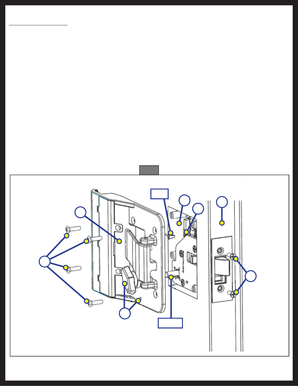
The following steps are graphically shown on the enclosed Bauer NE Installation schematic.
1. Remove old lock.
2. Clean cut-out. Remove any dirt, loose material, etc.
3. Install outside housing (the portion that includes the Touch Pad) with the dead bolt in the unlocked
position (Fig. 2A).
4. Attach the (2) 8x32 screws (Fig. 2B) into the portion of the handle that has the Plunger and Dead Bolt.
This is on the edge (Fig. 2C) of the door.
5. Plug wire from Inside Plate Assembly (Fig. 2D) into the receptacle (Fig. 2E) on the housing. Make sure
to align the tab on the plug properly with the slot on the receptacle. The plug should make a slight
click when properly engaged.
6. Tuck Battery Wires into pocket (Fig. 2F) next to Stamped Steel Plate. Do not allow Battery Wires to get
between Inside Plate Assembly and Stamped Steel Plate, as it will cause the motor to bind.
7. Align the Dead Bolt Knob in the unlocked position. The Red Dots on the Dead Bolt Knob and the Inside
Plate Assembly should be aligned to indicate the unlocked position of the Dead Bolt. Slide Dead Bolt
Knob over D-Stem and align the 4 screw bosses on the housing with the attaching holes on the Inside
Plate Assembly. When Inside Plate Assembly is in position with Housing, install the (4) 8x32 Screws.
Secure but do not over tighten screws (Fig. 2G).
Fig. 2
G
D
A
D Stem
C
Plug
F
E
B