Aftermarket manual – Lippert Components Shock Kit Aftermarket User Manual
Page 3
3
Shock Kit
Aftermarket Manual
www.lippertcomponents.com (574) 537-8900
Rev: 01.15 - Shock Kit Aftermarket Manual
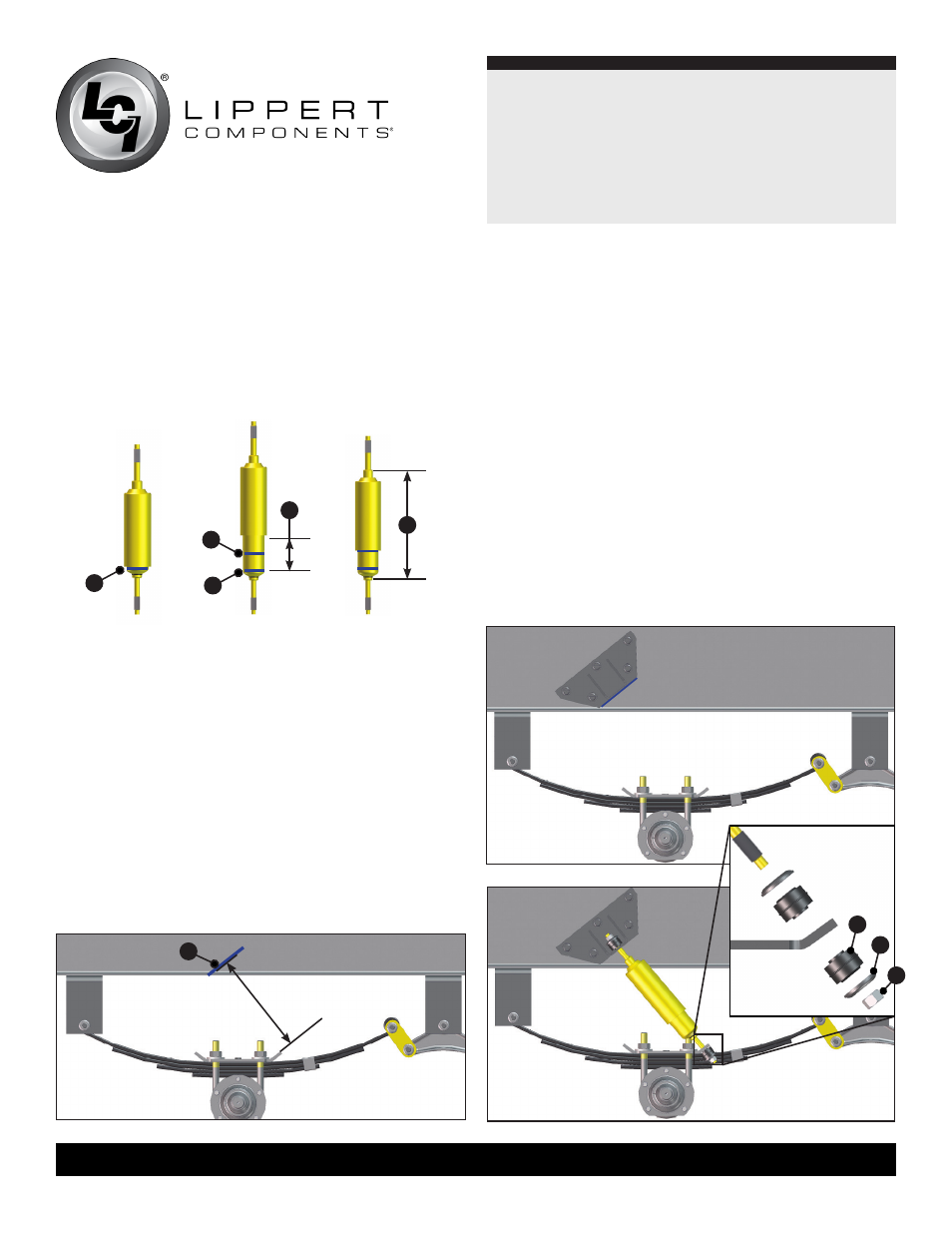
Fig. 2
Fig. 3
Fig. 4
Fig. 6
Fig. 8
4. Compress the shock (Fig.2) and make a mark on the inner
shock where the outer shock stops (Fig. 2A and 3A).
5. Release compression (Fig. 3). Measure the stroke (Fig. 3B)
and make a mark on the inner shock that is one half of the
stroke length (Fig. 3C).
6. Measure the shock length (Fig. 4A) when the shock is
compressed to the halfway mark made in Step 5 .
7 . Lower the trailer back down onto tires and level so the
equalizer(s), if equipped, are parallel to the frame and there is
a full load on the springs.
8. Make a measurement perpendicular to the shock mounting lip
on the tie plate that is the same distance measured in Step 6
(Fig.4A) + 2” and make a mark on the I-beam parallel to the
shock mounting lip on the tie plate (Fig. 5A).
NOTE:
Mount shocks pointing outwards (away from the shackle
kit, equalizer and/or center point) to get the best performance
from the shocks .
NOTE:
Dry fit the shock to be sure it does not exceed a 45 degree
angle or it will not function.
9. Align the bottom of the extended portion of the upper shock
mounting bracket to the mark made on the I-beam in Step 8
and drill 11/32” pilot holes.
10. Use the 3/8” self-tapping bolts to secure the upper shock
mounting bracket to the I-beam (Fig. 6).
11. Remove nut, washer and rubber grommet from both sides of
the shock .
12. Place the shock into the shock mounting lip on the tie plate
and compress it to fit into the upper mounting bracket.
13. Apply the rubber grommet (Fig. 7A), washer (Fig. 7B)
and nut (Fig. 7C) (in that order) and tighten to secure the
shock (Fig. 8).
NOTE:
Do NOT over-tighten. Tighten until the rubber grommet
(Fig. 7A) increases diameter equal to the washer (Fig. 7B).
A
A
C
B
A
Fig. 7
A
Fig. 5
B
C
A
Fig. 4A + 2”