Removing and replacing the flow switch (continued) – LAARS NeoTherm NTV (Sizes 399-850 MBTU/h) - Service Manual User Manual
Page 35
25
Service Manual - NeoTherm 500
Removing and Replacing the Flow Switch (continued)
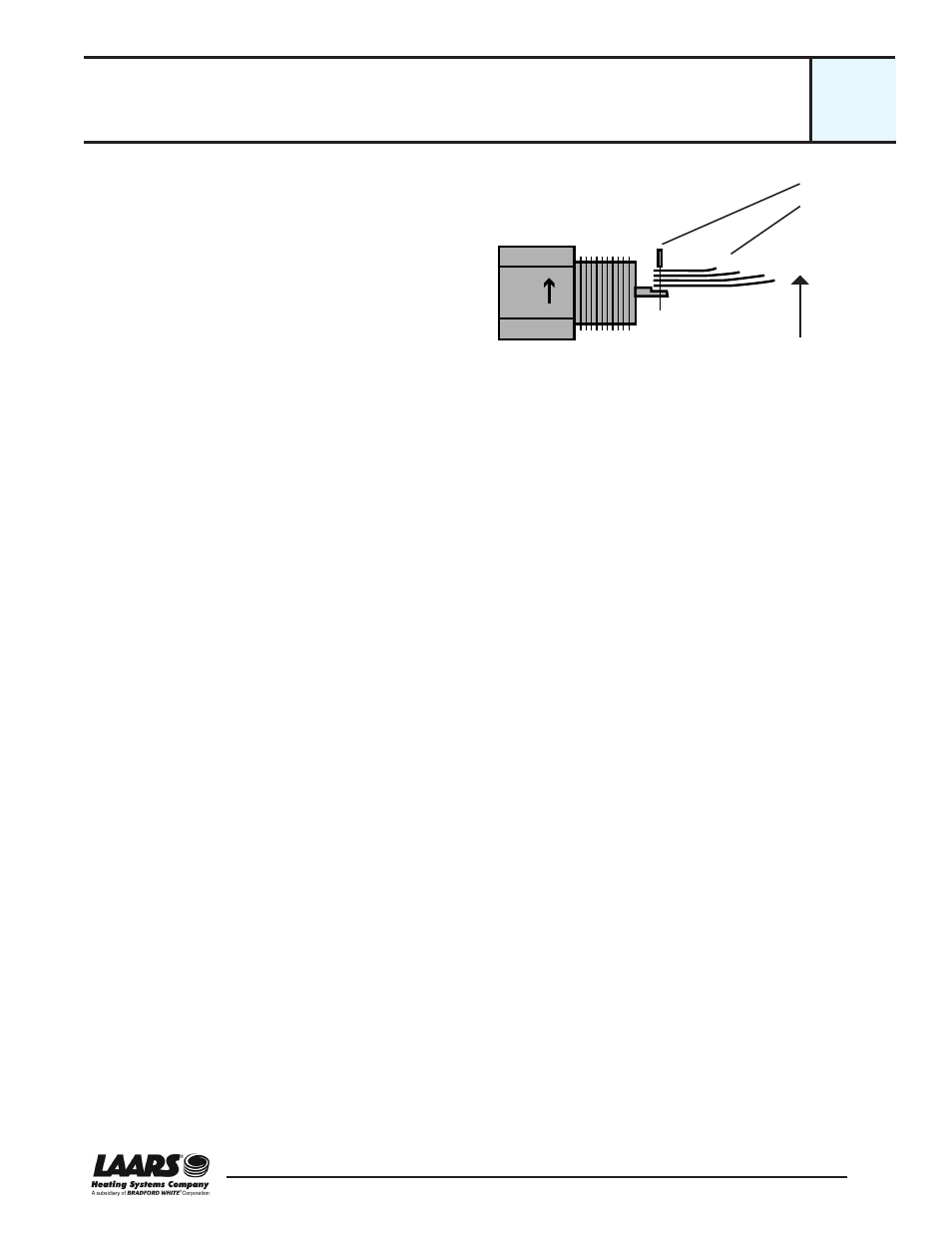
7. Once you have trimmed the paddles, install them
on the switch. See Fig. B10-1. Insert the pin to
attach the paddles to the center post.
8. Important! When the switch is installed, the ends
of the paddles must sit in the correct orientation
inside the pipe. The paddles must be placed so
they can sense the water flow, and they can bend
with the direction of the water flow.
• The wide sections of the paddles must sit
across the line of the water flow, partially block-
ing the flow.
• The flowing water should hit the longer paddle
first. See Fig. B10-1.
9. Note the arrow and the word “Flow” on the large
mounting nut. This will help you to install the
paddles in the correct orientation.
10. Coat the threads with pipe dope or Teflon® tape
and install the part.
Important! With the pipe wrench, tighten so the
paddles sit in the orientation shown above. Be
sure the arrow on the large mounting nut points
in the direction of water flow.
11. Re-connect the wires as shown in Fig. B9-3.
12. Open the water isolation valves and check for a
leak where the switch is threaded into the pipe.
13. Turn on power to the unit.
Paddles
Direction of
water flow
Pin
Fig. B10-1 - Attaching the paddles
B10
cont.
FLOW