LAARS Mighty Venter MV2 (Sizes 175-400) - Install and Operating Manual User Manual
Page 6
Page 6
LAARS Heating Systems
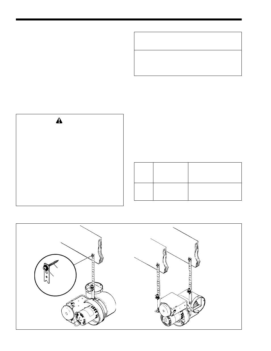
Figure 3. Power Venter Discharge Options.
To facilitate installation and reduce vibration, 2
mounting brackets, 2 rubber isolators, and 2 rubber
grommets are included. One of the brackets can be
used as a temporary “third hand” while positioning it
for permanent installation (see Figure 3).
When installing the Power Venter for horizontal
discharge, install one of the brackets to the electrical
box using the nut/screw provided. Install the other to
the damper rod. When installing the Power Venter for
vertical discharge, only one bracket is needed. Mount
this bracket to the motor as shown in Figure 3.
SECTION 3.
Electrical Wiring
WARNING
All wiring from the Power Venter to the appliance
must comply with local codes, or in their absence,
the National Electric Code (NFPA #70) in the United
States and/or CSA C22.1 Electrical Code in
Canada.
Disconnect 115 VAC power to the appliance before
proceeding with wiring the Power Venter. The power
can be disconnected by tripping the circuit breaker
or removing the fuse protecting the appliance.
All wiring must comply with applicable codes and
ordinances. All 115 VAC wiring must be rigid or
semi-rigid metal conduit with 18 AWG, 300 VAC,
90° C rated copper wire.
Wire the hot water boiler and the Power Venter
exactly as shown in Figure 7 and follow these steps:
1. Connect the black and white (115 VAC) wires
from the Power Venter to the boiler control box as
shown in Figure 7.
2. Connect the red, blue and yellow (24 VAC)
wires to the terminal block as shown in Figure 7.
Make sure the current capacities of the wires,
switches, etc. at 115 VAC meet the ratings in Table 3.
3. Remove factory-installed jumper from
between boiler terminals 3 and 4.
Equivalent Full Load
Power Venter
Currents
Model
Motor HP
(Amps - 115 VAC)
MV1
1/25
1.3
MV2
1/8
4.4
Table 3. Electrical Ratings.
Boiler
Vent
Vent
Fig. Boiler Draft Hood Pipe
Hood
Rough-in
No.
Size
Outlet
Dia.
Dia.
Dim.
4
175
6"
4"
4"
8.0" Dia.
5
250
7"
6"
6"
9.0" Dia.
6
325
8"
6"
6"
9.0" Dia.
6
400
9"
6"
6"
9.0" Dia.
Table 2.