1b. vent sizing, 1c. inspection and unpacking, 1d. installer information – LAARS Mighty Venter MV2 (Sizes 175-400) - Install and Operating Manual User Manual
Page 3: Mighty venter power vent system
Mighty Venter Power Vent System
Page 3
SECTION 1.
1a. General Information
WARNING
The MV1 and MV2 Mighty Venter must be installed
in accordance with the procedures outlined in these
instructions. Warranty applies only if the installation
and operating instructions applicable to the model
purchased are expressly and completely followed.
The Laars Mighty Venter, Models MV1 and
MV2, are designed to make side-wall venting possible
for Laars hot water boilers, Models HH, PH, VW and
PW, sizes 175 - 400. Both the MV1 and MV2 are
equipped with a fan-prover switch which disables the
gas valve if the Power Venter fails to operate.
The Mighty Venter installation must comply with
the latest edition of the National Fuel Gas Code, ANSI
Z223.1, and in Canada, CAN1-B149.1 or .2 and all
local codes that apply. The installation must include
the draft hood assembly shipped with the boiler,
including vent damper if required.
1b. Vent Sizing
Take into consideration the dimensions in Table 1
when designing the vent system. The vent pipe length
shown includes all vent pipe before and after the
Power Venter.
1c. Inspection and Unpacking
Immediately upon receiving the Mighty Venter
kit, inspect the shipment packaging for damage.
Record any damage on the shipping documents.
Unpack the equipment and carefully inspect it for
obvious damage caused in shipment. If any damage is
found, YOU must file a claim with the transporter. The
transporter will not accept a claim from the shipper,
Laars Heating Systems.
The Mighty Venter kit includes three cartons:
Carton 1. Power Venter (MV1 or MV2)
Carton 2. Vent Hood
Carton 3. Vent Reducers/Adapter
Verify the contents of each carton by checking
against the parts list on page 8.
1d. Installer Information
1.
Before beginning the installation, read these
instructions completely and make sure each part
is placed to safely vent flue gases to the
outdoors.
2.
Carefully read the installation instructions
located in the Side Wall Vent Hood carton.
3.
Laars does not provide the vent pipe necessary
for this installation. Use Table 1 as an aid in
selecting the proper vent pipe diameter.
4.
Locate the Power Venter as close as possible to
the point of termination (i.e., the wall). This will
insure the vent pipe between the boiler and the
Power Venter inlet is under negative pressure.
5.
Make sure the power supply is adequate for the
Power Venter motor requirements. Do not add
the Power Venter to a circuit where the total load
is unknown.
Caution
To prevent personal injury and equipment damage,
disconnect the power supply to the hot water boiler
when working on the Power Venter.
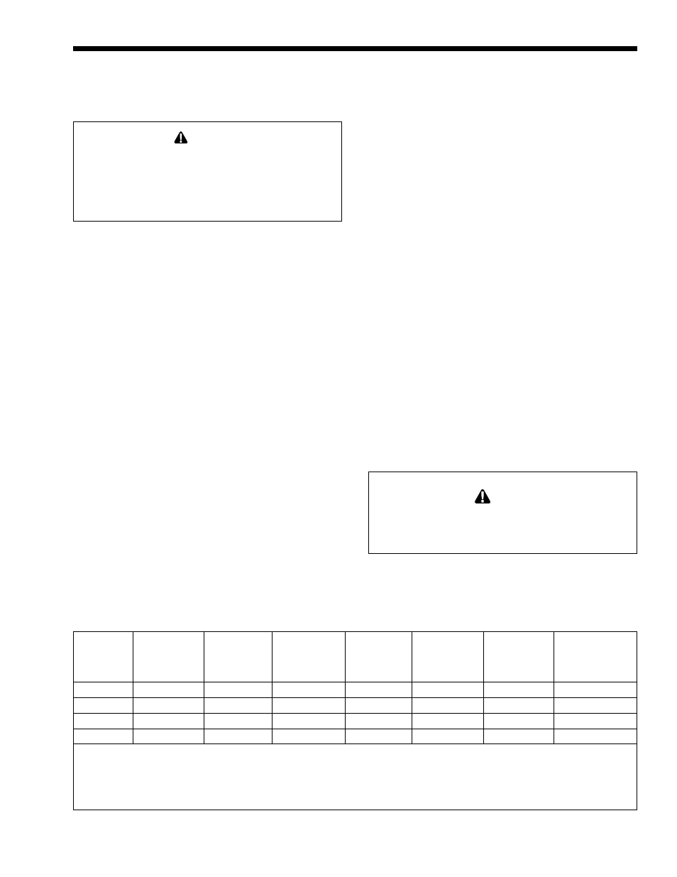
Table 1. Critical Vent Sizing Data.
Notes:
1. Table 1 is for single boiler installations only.
2. To calculate the equivalent vent pipe length, add the length of the straight pipe plus 10 feet (3.0m) for every
90° elbow and 5 feet (1.5m) for every 45° elbow.
3. Vent pipe reducers will be supplied by Laars.
Minimum
Maximum
Mighty
Boiler/
Mighty Venter
Boiler/Heater
Vent Pipe
Equivalent
Equivalent
Mighty Venter
Venter
Heater
Order Number
Outlet Diameter
Diameter
Pipe Length
Pipe Length
Diameter
Model
Size
in
mm
in.
mm
feet
m
feet
m
in
mm
MV1
175
10718702
6
152
4
102
11
3.4
90
27.4
4
102
MV1
250
10718703
7
178
6
152
11
3.4
100
30.5
4
102
MV2
325
10718704
8
203
6
152
11
3.4
100
30.5
6
152
MV2
400
10718705
9
229
6
152
11
3.4
100
30.5
6
152