LAARS POWER VENTED GAS WATER HEATER - Installation Manual User Manual
Page 12
12
Venting (Part I) continued-
TABLE 2 -VENT CONNECTOR LENGTHS
FOR 4” (10.2 cm) DIAMETER VENT PIPE
Maximum straight
Length ft (m)
Terminating
# of 90
°
Elbows (excl.
vent term.)
48, 65 gal.
Min
straight
Length
ft (m)
Through the Wall
1 175
(53.3)
10 (3.1)
Through the Wall
2 170
(51.8)
10 (3.1)
Through the Wall
3 165
(50.3)
10 (3.1)
Through the Wall
4 160
(48.8)
10 (3.1)
Through the Wall
5 155
(47.2)
10 (3.1)
Through the Roof
0 180
(54.9)
15 (4.6)
Through the Roof
1 175
(53.3)
15 (4.6)
Through the Roof
2 170
(51.8)
15 (4.6)
Through the Roof
3 165
(50.3)
15 (4.6)
Through the Roof
4 160
(48.8)
15 (4.6)
NOTE: When using 4” (10.2 cm) vent pipe, use a 4” (10.1 cm) to 3” (7.6
cm) reducer and exit the building wall with 3” (7.6 cm) vent pipe using the
3” (7.6 cm) 90
° vent terminal supplied. Two 45° elbows are equivalent to
one 90
° elbow.
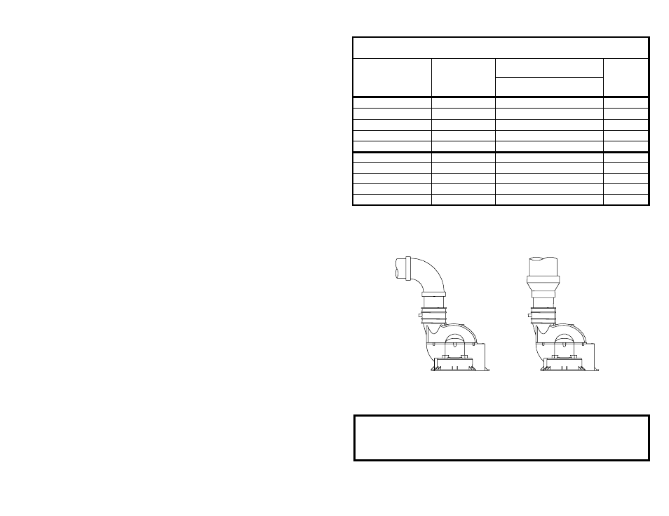
CONNECTION TO A 3” (7.6 CM) TO
4” (10.2 CM) REDUCER
CONNECTION TO 3” (7.6 CM)
VENT PIPE
Figure 2
IMPORTANT
All of the Venting connections must be leak checked with a soap and
water solution upon initial start up of the water heater. Any leaks must
be repaired before continuing operation of the water heater.