System led, Rps led, Master led – Cisco 2975 User Manual
Page 12: Port leds and modes, Master led port leds and modes
1-4
Catalyst 2975 Switch Hardware Installation Guide
OL-17784-01
Chapter 1 Product Overview
Front Panel
System LED
For information on the System LED colors during power-on self-test (POST), see the
.
RPS LED
For more information about the Cisco RPS 2300 or the Cisco RPS 675, see the
section.
Master LED
Port LEDs and Modes
Each port and module slot has a port LED. As a group or individually, the LEDs show information about
the switch and about the individual ports.
lists the mode LEDs and their associated port modes
and meanings.
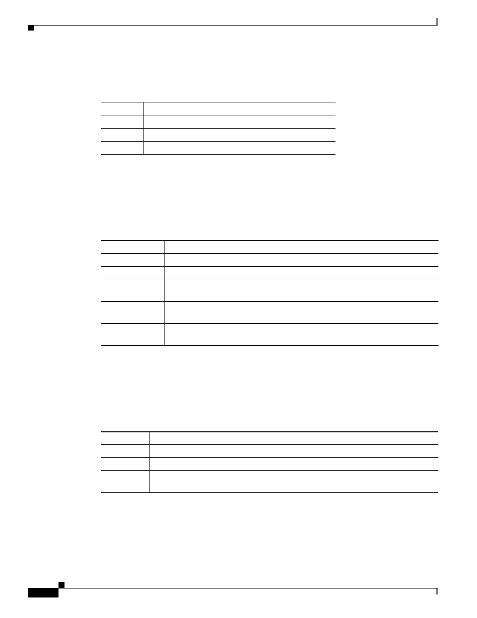
Table 1-2
System LED
Color
System Status
Off
System is not powered on.
Green
System is operating normally.
Amber
System is receiving power but is not functioning properly.
Table 1-3
RPS LED
Color
RPS Status
Off
RPS is off or not properly connected.
Green
RPS is connected and ready to provide back-up power.
Blinking green
RPS is connected but is unavailable because it is providing power to another device
(redundancy has been allocated to a neighboring device).
Amber
The RPS is in standby mode or in a fault condition. See the RPS documentation for
more information about the standby mode and fault conditions.
Blinking amber
The power supply in a switch has failed, and the RPS is providing power to the
switch (redundancy has been allocated to this device).
Table 1-4
Master LED
Port Mode
Description
Off
Switch is not the stack master.
Green
Switch is the stack master or a standalone switch.
Amber
An error occurred when the stack was electing the stack master switch, or another type
of stack error occurred.