Controls/component locations – Century OPERATING INSTRUCTIONS CEXT7 User Manual
Page 9
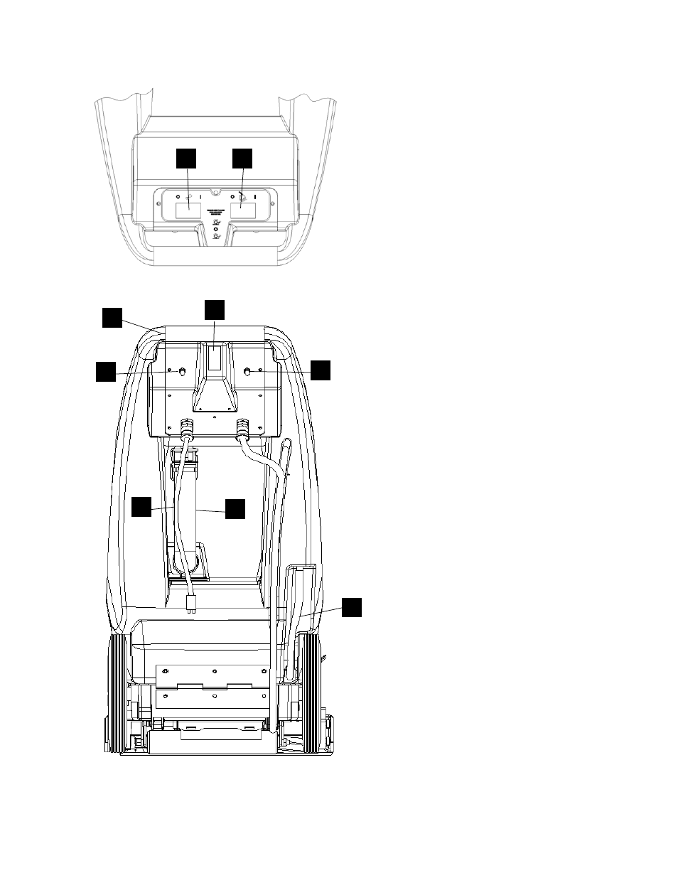
CONTROLS/COMPONENT LOCATIONS
86037910 CEXT7 03/23/07
3-2
1. Main Handle. Used to pull and maneuver
machine.
2. Electrical
Cord.
3. Pump
Switch. Turns on pump and enables
spray.
4. Brush/Spray
switch. Turns on brush motor
and activates electro-valve to dispense solution
to floor through jets. Intermittent, off, and
continuous settings.
5. Vacuum Motor Switch. Turns on vacuum
motor
6. Brush Motor Circuit Breaker. 6 amp. Breaker
protecting brush motor.
7. Vacuum Motor Circuit Breaker. 15 amp.
Breaker protecting vacuum motor.
8. Recovery Dump Hose. Facilitates draining
dirty cleaning solution.
9. Solution Dump Hose. Facilitates draining
excess cleaning solution from solution tank.
2
1
4
6
7
8
9
3
5