Installation mode “a” (most vehicles), Mode a – Crimestopper Security Products CS-883 OEM User Manual
Page 6
6
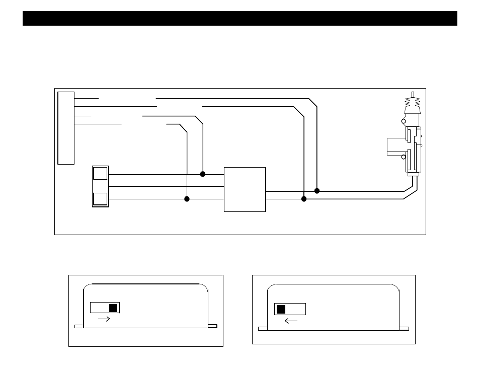
NEGATIVE VALIDATION INPUTS
(TOP EDGE OF 883 MODULE)
POSITIVE VALIDATION INPUTS
(TOP EDGE OF 883 MODULE)
INSTALLATION MODE “A” (Most Vehicles)
MODE A
is the default mode and is used for most vehicles.
This mode requires 4-Wires to be connected for proper operation: Yellow/Black and Blue/Black connect to the
(+) 12V solenoid lock & unlock wires. Green/White and Brown connect to the factory door lock switch. The
polarity (+/-) of the Green/White and Brown wires can be changed by using the slide switch on the top of the CS-
883OEM module. See Diagrams below for standard MODE “A” installation.
L
U
FACTORY
POWER
LOCK
RELAYS
LOCK
SWITCH
(+) LOCK / MOTOR WIRE
(+) UNLOCK / MOTOR WIRE
YELLOW / BLACK
BLUE / BLACK
GREEN / WHITE
BROWN
+ / - LOCK SWITCH WIRE *
+ / - UNLOCK SWITCH WIRE *
(*Programmable for POS/NEG validation)
The slide-switch on the top of the module determines the polarity of Green/White and Brown “Validate” Wires.
Connecting the Green/White and Brown “Validation” wires to the factory door lock switch prevents an intruder or
thief from arming or disarming the system by pressing the lock/unlock button on the vehicle door panel.