Step 5: test run your new rear view camera system – Crimestopper Security Products SV-6600 I/R User Manual
Page 5
1770 SOUTH TAPO STREET
ª
SIMI VALLEY, CALIFORNIA 93063
800-998-6880
ª
805-526-9400
ª
FAX 805-581-9500
Page 5 of 6
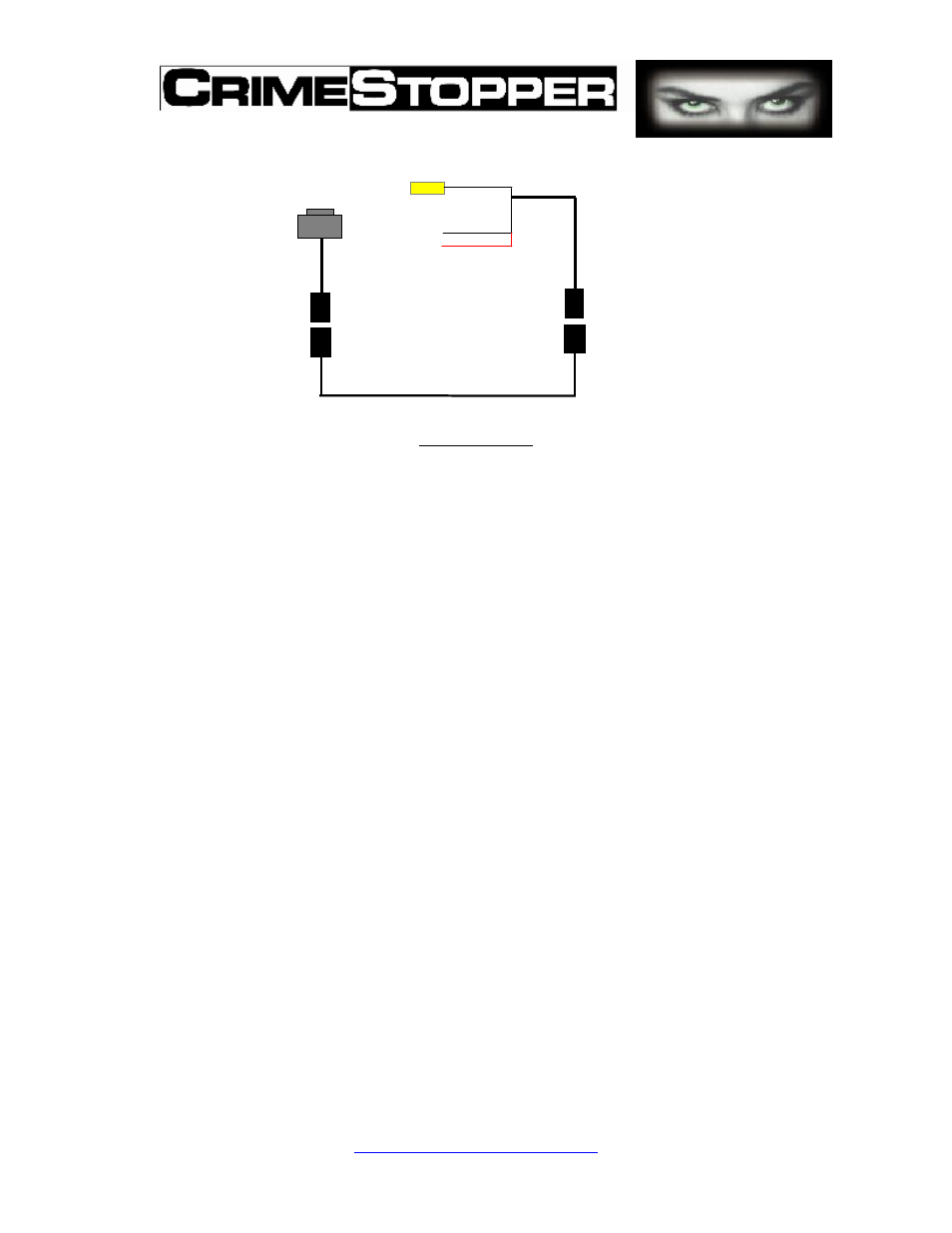
Video output to monitor
Diagram 4.1-3
2. In most cases and as a time saver, connect the camera power wire at the rear of
vehicle behind the reverse lights. The red power wire line goes to the reverse
light + 12 V and the black wire to ground.
3. Please carefully choose a path to route and hide the camera cable. Drilling a cable
hole if necessary.
4. Please make sure to use the rubber grommet or plug to make a watertight seal for
the cable where it passes into the vehicle body.
5. Please refer to the monitor wiring diagram. The monitor must be connected using
its own power line and should not be connected to same power line with the
camera.
Step 5: Test Run Your New Rear View Camera System
1. You have just completed the installation and wiring of your new rear view camera
system.
2. Please make sure the vehicle is parked at a safe place before you do a test run.
3.
Power up your vehicle and the monitor. Put the vehicle in reverse and the monitor
should immediately display a clear, color picture.
Important: The rear view camera will be used when the vehicle is in reverse gear. If the monitor
does not display a picture or the picture quality not satisfactory, please double check all cable
connections. If you are unable to correct the problem, please contact your supplier for help.
I/R Camera
Black, Ground
Red, power input 12V (+) from reverse light
12 PIN (M)
12 PIN (F)
4 PIN (M)
4 PIN (F)