Step 3: camera installation, Step 4: wire connection, 4 pin connector – Crimestopper Security Products SV-6600 I/R User Manual
Page 4
1770 SOUTH TAPO STREET
ª
SIMI VALLEY, CALIFORNIA 93063
800-998-6880
ª
805-526-9400
ª
FAX 805-581-9500
Page 4 of 6
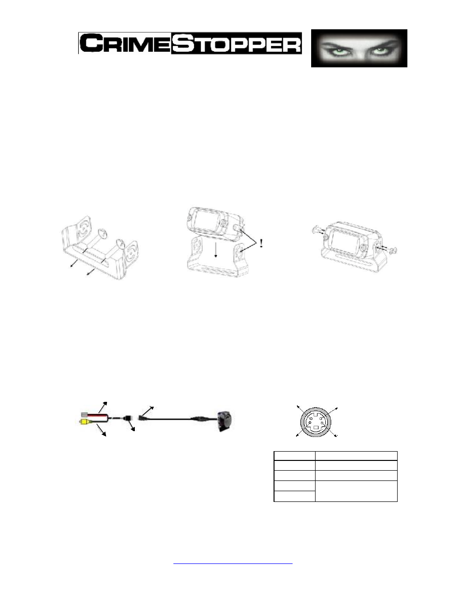
Step 3: Camera Installation
1. Determine the proper location on your vehicle to install the camera.
2. Make sure the area surface is clear, clean and flat.
3. Install the mounting bracket. (Refer to Diagram 3.1-1)
4. Assemble the camera inside of the mounting bracket (Refer to
Diagram 3.1-2)
5.
Adjust the viewing direction and angles to attain the best viewing (Refer to
Diagram 3.1-3)
Diagram 3.1-1
Diagram 3.1-2
Diagram 3.1-3
④
Step 4: Wire Connection
1. Connect the power source line to the camera. Also connect 20’ cable to the
monitor. (Refer to Diagram 4.1)
4 pin connector
Pin No.
PART-DESC
1
Video Output
2
Power DC 12V
3
GND
4
2
1
4
3
Diagram 4.1-1
Diagram 4.1-2
RED Power Input 12V(+)
BLACK Power Input 12(-)
Waterproof Camera
Connector
Video Output
Standard Cable Connector