Save these instructions, Pool setup (continued), English page 6 – Intex 32FT X 16FT X 52IN RECTANGULAR POOL SET 2014 User Manual
Page 6
119
PO
SAVE THESE INSTRUCTIONS
(119PO) RECTANGULAR ULTRA FRAME POOL ENGLISH 7.5” X 10.3” PANTONE 295U 07/18/2013
English
Page 6
POOL SETUP (continued)
You may have purchased this pool with the Intex Krystal Clear™ filter pump. The pump has its
own separate set of installation instructions. First assemble your pool unit and then set up the
filter pump.
Estimated assembly time 60~90 minutes. (Note the assembly time is only approximate and
individual assembly experience may vary.)
• Find a flat, level location that is free and clear of stones, branches or other sharp objects that may
puncture the pool liner or cause injury.
• Open the carton containing the liner, joints, legs, etc., very carefully as this carton can be used to store
the pool during the winter months or when not in use.
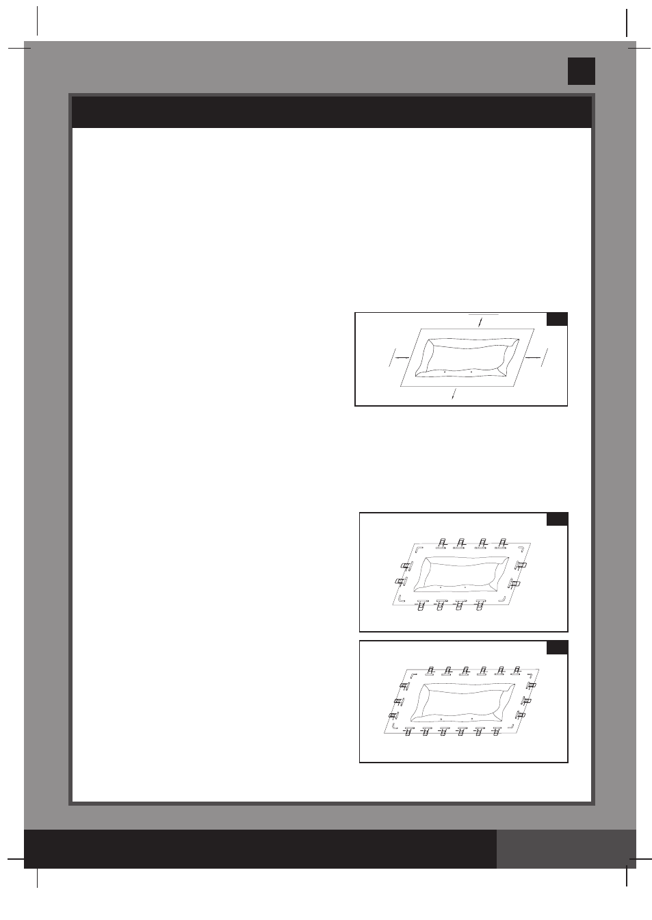
• Remove the ground cloth
(14) from carton. Spread it
out completely with its edges being at least 5 - 6’
(1.5 - 2.0 m) from any obstacle such as walls, fences,
trees, etc. Remove the liner
(15) from carton and
spread it out over the ground cloth with the drain valve
towards the draining area. Place the drain valve away
from the house. Open it up to warm it in the sun. This
warming will make installation easier. Make sure the
liner is centered atop the ground cloth. Be sure to face
the end with the 2 hose connectors towards the electrical power source.
IMPORTANT: Do not drag the liner across the ground as this can cause liner damage and pool
leakage (see drawing 1).
• During the set-up of this pool liner, point the hose connections or openings in the direction of the electric
power source. The outer edge of the assembled pool is to be within reach of the electrical connection for
the optional filter pump.
2. Remove all the parts from the carton(s) and place them
on the ground in the location where they are to be
assembled. Check the parts listing and be sure all the
pieces to be assembled are accounted for (see
drawings 2.1, 2.2 & 2.3).
IMPORTANT: Do not start assembly if any pieces
are missing. For replacement pieces call the
Consumer Service telephone number in your area.
After all pieces are accounted for move the pieces away
from the liner for of installation.
1
ELECTRICAL SOURCE
5 - 6' (1.5 - 2.0 m)
5 - 6'
(1.5 - 2.0 m)
5 - 6'
(1.5 - 2.0 m)
LINER
2.1
157-1/2”x78-3/4”x39-3/8” /15’ X 9’ / 18’ X 9’
(A)
CORNER JOINT
CORNER JOINT
CORNER JOINT
CORNER JOINT
(F)
(D)
(F)
(D)
(C)
(A)
(C)
LINER
(B) (B)
(B)
(B)
2.2
(A)
CORNER
JOINT
CORNER
JOINT
CORNER
JOINT
CORNER
JOINT
(F)
(D)
(E)
(D)
(F)
(E)
(C)
LINER
(B) (B)
(B) (B)
(C)
(A)
(B) (B)
(B) (B)
24’ X 12’