Cabletron Systems Expansion module 9E106-06 User Manual
Page 40
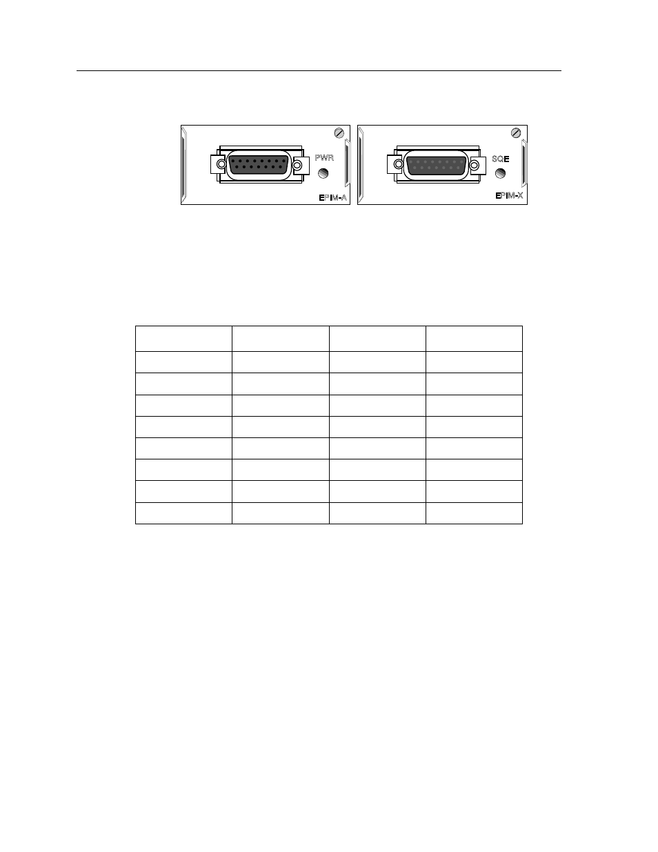
EPIMs
A-6
Figure A-5. The EPIM-A and EPIM-X
Table A-4 lists the DB-15 pinouts.
Table A-4. DB-15 Pinouts
Pin Number
Represents
Pin Number
Represents
1
Logic Ref.
10
Transmit -
2
Collision +
11
Logic Ref.
3
Transmit
12
Receive -
4
Logic Ref.
13
Power (+12Vdc)
5
Receive
14
Logic Ref.
6
Power Return
15
No Connection
7
No Connection
Connector Shell
Positive Ground
9
Collision -
See also other documents in the category Cabletron Systems Hardware:
- FOT-F3 (41 pages)
- FOT-F3 (44 pages)
- BRIM-F6 (41 pages)
- WPIM-RT1 (50 pages)
- BRIM-WT1 (32 pages)
- 36 (33 pages)
- 9T101-04 (28 pages)
- FDDI Repeater (29 pages)
- SWPIM-BRI (34 pages)
- 9C114 (26 pages)
- SMARTSWITCH ROUTER 9032578-05 (398 pages)
- HSIM-W6 (258 pages)
- NB25 E (30 pages)
- HSIM-G01 (36 pages)
- HSIM-FE6 (42 pages)
- Expansion module 9E429-36 (18 pages)
- EMM-E6 Ethernet (205 pages)
- Environmental Module TM 9C300-1 (50 pages)
- CSMIM-T1 (198 pages)
- NBR-620 (73 pages)
- E2100 (42 pages)
- KBU64 Rackmount (26 pages)
- AirConnect 3Com (93 pages)
- 802.1Q (92 pages)
- W85 (60 pages)
- ELS10-26 (170 pages)
- 6H259-17 (58 pages)
- Expansion module 9F120-08 (12 pages)
- EMC39-12 (33 pages)
- 6A000/ZX-250 (268 pages)
- Expansion module DELHE-UA (50 pages)
- Expansion module 9T122-08 (36 pages)
- DMS-100 (196 pages)
- BRIM E100 BRIM-E100 (42 pages)
- Cabletron CyberSWITCH CSX400 (275 pages)
- Cabletron SmartSwitch Router 250 (34 pages)
- Network Router (100 pages)
- 9W111-08 (28 pages)
- CSX400 (101 pages)
- Cabletron SmartSwitch Router 510 (106 pages)
- SEHI-32/34 (90 pages)
- SmartSwitch (338 pages)
- 9T106-01 (28 pages)
- Switch 9H531-17 (38 pages)