Cabletron Systems Expansion module 9E106-06 User Manual
Page 30
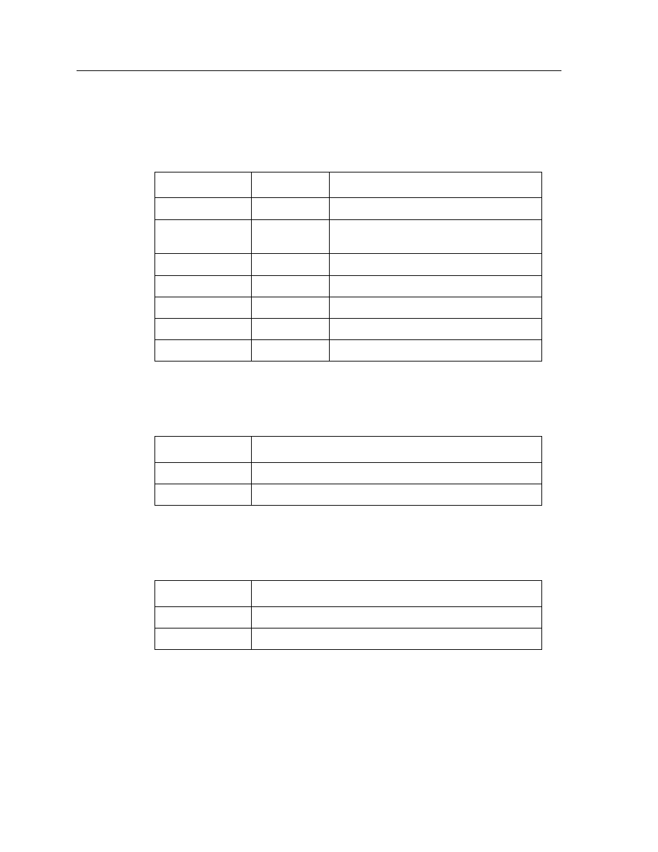
LANVIEW LEDs
4-2
The functions of the System Management Bus (SMB) and CPU LEDs are listed in
Table 4-1.
The functions of the FNB Receive LED are listed in Table 4-1.
The functions of the FNB Transmit LED are listed in Table 4-3.
Table 4-1. SMB and CPU LEDs
LED Color
State
Description
Green
Functional
Fully operational.
Yellow
Testing
Normal, internal diagnostic testing being
done.
Yellow (Flashing)
Crippled
Not fully operational (i.e., one bad port).
Yellow/Green
Booting
Blinks yellow and green while booting.
Red
Reset
Normal power-up reset.
Red (Flashing)
Failed
Fatal error has occurred.
Off
Power off
Module powered off.
Table 4-2. FNB Receive LEDs
LED Color
State
Yellow (Flashing)
Activity (Flashing rate indicates rate of activity.)
Off
No activity
Table 4-3. FNB Transmit LEDs
LED Color
State
Green (Flashing)
Activity (Flashing rate indicates rate of activity.)
Off
No activity
- FOT-F3 (41 pages)
- FOT-F3 (44 pages)
- BRIM-F6 (41 pages)
- WPIM-RT1 (50 pages)
- BRIM-WT1 (32 pages)
- 36 (33 pages)
- 9T101-04 (28 pages)
- FDDI Repeater (29 pages)
- SWPIM-BRI (34 pages)
- 9C114 (26 pages)
- SMARTSWITCH ROUTER 9032578-05 (398 pages)
- HSIM-W6 (258 pages)
- NB25 E (30 pages)
- HSIM-G01 (36 pages)
- HSIM-FE6 (42 pages)
- Expansion module 9E429-36 (18 pages)
- EMM-E6 Ethernet (205 pages)
- Environmental Module TM 9C300-1 (50 pages)
- CSMIM-T1 (198 pages)
- NBR-620 (73 pages)
- E2100 (42 pages)
- KBU64 Rackmount (26 pages)
- AirConnect 3Com (93 pages)
- 802.1Q (92 pages)
- W85 (60 pages)
- ELS10-26 (170 pages)
- 6H259-17 (58 pages)
- Expansion module 9F120-08 (12 pages)
- EMC39-12 (33 pages)
- 6A000/ZX-250 (268 pages)
- Expansion module DELHE-UA (50 pages)
- Expansion module 9T122-08 (36 pages)
- DMS-100 (196 pages)
- BRIM E100 BRIM-E100 (42 pages)
- Cabletron CyberSWITCH CSX400 (275 pages)
- Cabletron SmartSwitch Router 250 (34 pages)
- Network Router (100 pages)
- 9W111-08 (28 pages)
- CSX400 (101 pages)
- Cabletron SmartSwitch Router 510 (106 pages)
- SEHI-32/34 (90 pages)
- SmartSwitch (338 pages)
- 9T106-01 (28 pages)
- Switch 9H531-17 (38 pages)