Installation, See fig. 2 on page 3 – Philips AZ 9855 User Manual
Page 3
Attention! The text in this document has been recognized automatically. To view the original document, you can use the "Original mode".
3. INSTALLATION
- see fig. 2 on page 3
POWER SUPPLY
REMOVABLE SPEAKERS
Battery supply
Whenever convenient, use the mains supply if
you want to conserve battery life.
•
Open the battery compartment and insert as
shown eight batteries, type R20, UM1 or D-
cells.
•
Remove the batteries if exhausted or if they
will not be used again for a long period.
The battery supply is switched off when the
set is connected to the mains. To change over
to battery supply, pull out the plug from the
MAINS socket.
Mains supply
• Check if the mains voltage as shown on the
type plate (on the back of the set) corres
ponds to your local mains voltage. If it does
not, consult your dealer or service organisa
tion.
If the set is equipped with a VOLTAGE
selector 19, set this selector to the local
mains voltage.
•
Connect the mains lead to the MAINS
socket and the wall socket.
When connected to the mains, the system is
always energised.To switch off the mains
supply completely, pull the mains plug out of
the wall socket.
Taking off the speakers
• Keep the UNLOCK lever pressed and slide
the speaker upwards, see fig. 2.
Attaching the speakers
• Slide the speakers from above in the
sleeves on the sides of the system cabinet.
The speakers will click into position.
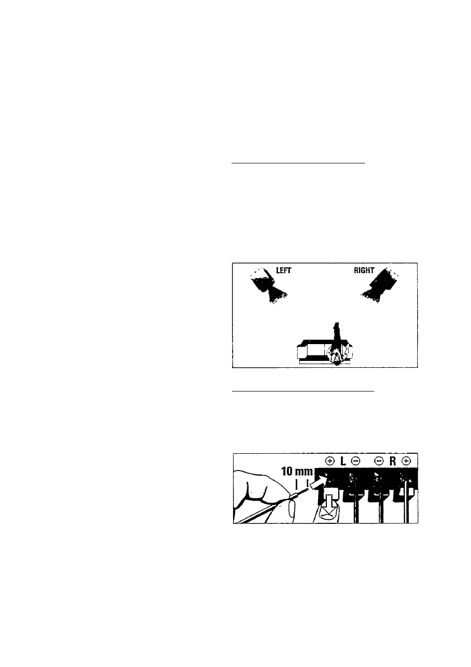
POSITIOIMING THE SPEAKERS
You will find the best speaker position by
experimenting. Placing the speakers on the
floor will increase the bass response. Placing
the speakers behind curtains, furniture etc. will
reduce the treble response and the stereo
effect. The ideal position is obtained when the
2 front speakers and the listening position
build an equilateral triangle and the speakers
are at ear-height.
o>
c
u
COIMIMECTIIMG THE SPEAKERS_________
You can connect the 2 supplied speakers or
others having an impedance of 4 Ohms.
• Connect the black or non-marked wires to
the black terminals © and the red or marked
wires to the red terminals ®.