ISP Technologies VECTOR 210 User Manual
Page 6
7. GROUND LUG
Grounding Options
The VECTOR 210 is designed to allow interconnection to all makes and
models of amplifiers available including amplifiers with Bridge Mode
operation. A Bridge Mode amplifier design offers higher output signal swing
because one channel drives the positive terminal of a speaker in phase and a
second channel drives the negative terminal of the speaker with an inverted
signal. In order to accept connection with Bridge Mode amplifiers the
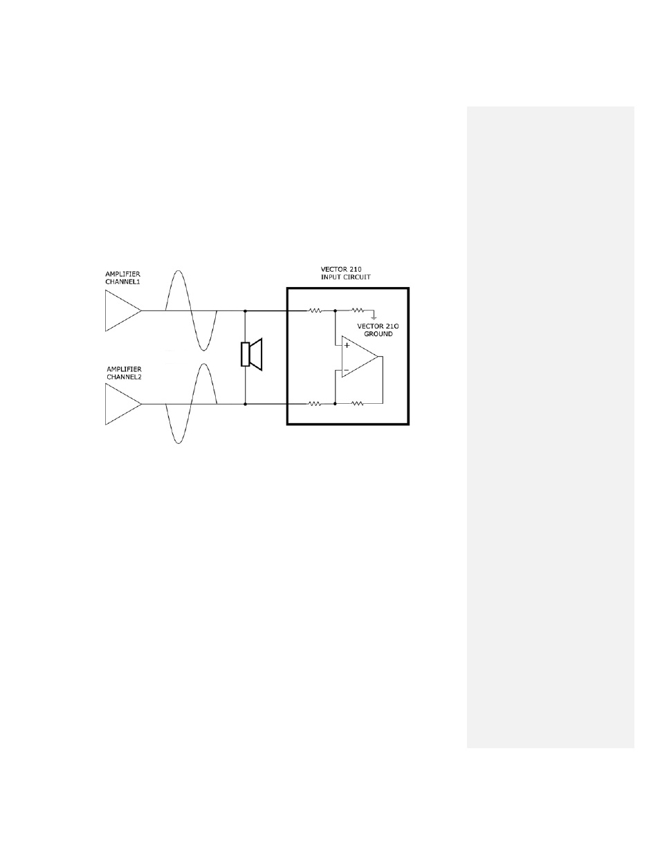
VECTOR 210 input circuit is a true differential floating input. The picture
below shows the connection between a differential Bridge Mode amplifier and
the floating Differential Input circuit of the VECTOR 210.
There is not a common ground connection as there would be with a single-
ended input connection. In most applications, the ground pin on the AC
power cable will provide a common ground between the two units.
To ensure safety, it is important to never cut or remove the ground pin on a
power cable and be sure every unit is connected to a common ground in the
system.
If, however, the amplifier is floating with respect to power ground and the
pre-amplifier or pedals used are also floating and do not provide a connection
to power ground, a ground buzz can occur. This ground buzz can be
eliminated by connecting a ground wire between the rear panel ground tab
and the ground of the input circuit or preamplifier. If you are unclear on how
to make this connection or have questions, contact ISP directly for more
details.
NOTE: The VECTOR 210 provides automatic protection against
connecting a speaker level input signal with the Attenuation Switch
set in line level position. If the input signal exceeds the maximum
line level of +20dbu, the VECTOR 210 will attenuate and mute the
output signal to avoid damaging the internal amplifier or speaker. If
this happens, switch the Input Attenuator switch to the Speaker
Input setting and the VECTOR 210 will operate after a 20 second
mute time period.