Interlogix 3050 Series User Manual
Page 2
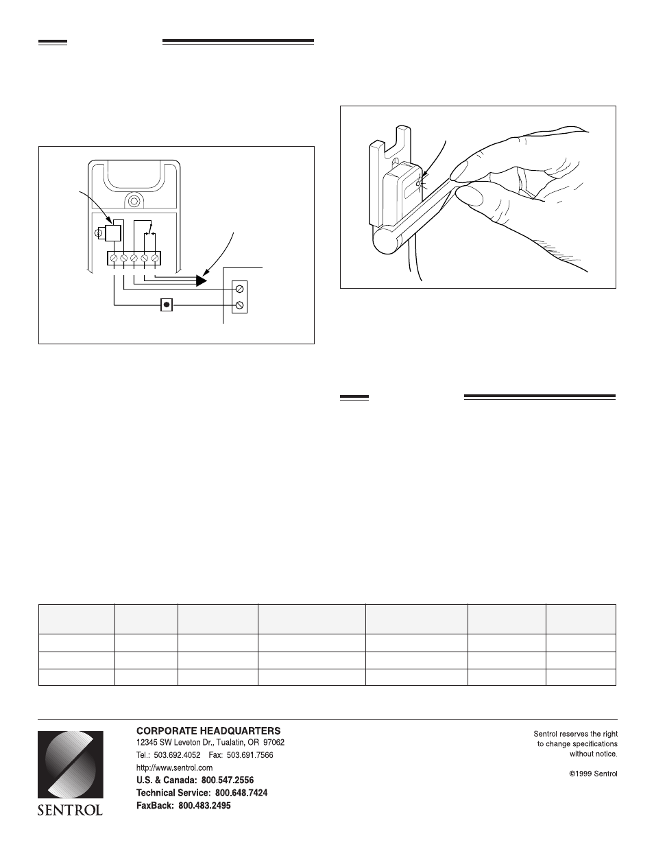
The wiring diagrams show two separate circuits: the SPDT
circuit and the latching LED circuit. The latching LED must be
powered and controlled by, respectively, a +12 VDC source in
the alarm panel (24 hour switchable power loop or equivalent),
and a normally closed push-button or spring-loaded momentary-
action toggle switch inside or mounted outside the panel. Wire
the reset circuit in series to the LED circuit as shown.
To test and rearm the SPDT switch, do the following:
1. Pull the handle down until the LED lights or changes to red
(3050), indicating that the SPDT alarm circuit has been acti-
vated.
2. Close the handle. The SPDT switch is now fully re-armed.
The LED remains lit.
3. Activate the normally closed push-button or toggle switch
located at the master control panel to interrupt power to the
latching LED. The LED will go out or change to green (3050).
Nominal Voltage .................................................. 12 VDC @ 6mA
Operational Voltage ........................................... 7 VDC - 15 VDC
Current Draw ................................................................. Max 8mA
Temperature ....................................... 0° to 110°F (-18° to 48°C)
Dimensions . 1.77" (4.50cm) W x 2.90" (7.37cm) L x .76" (1.93cm)
D
Weight ................................................................................ 1.5 oz.
Housing Material ........................................................ ABS plastic
STEP 2 - WIRING
When the actuating lever is pulled between 20° to 45°, the alarm
circuit switch (SPDT) will actuate. Then the LED will latch and
light or change to red (3050), indicating that the SPDT switch
has been activated. Closing the handle rearms the SPDT switch.
However, the LED remains lit.
IMPORTANT: The lever must be closed first to reset the
SPDT circuit before the LED is reset.
SPECIFICATIONS
+ – COM N.C. N.O.
–
+
LED Latches
and Lights
To N.C. and
N.O. Connections
(12 VDC)
LED Reset
(N.C. Push Button)
Latching
LED
Circuit
C-3732-0299
14327 Rev B
* European Union Specification: 48 V AC/DC Max., 0.5 Amp
Lead Colors for 3040CT, 3050CT Form C
Green
Common
Brown
Closed Loop (N.O.)
White
Open Loop (N.C.)
Red
Positive
Black
Negative
Model
Latching
Electrical
Number
LED
Circuit
Loop Type
Configuration
Color
Listed
3040
Red
Yes
Open or Closed
SPDT
White
UL
3040CT
Red
Yes
Open or Closed
SPDT
White
UL
3050
Bi-color
Yes
Open or Closed
SPDT
White
UL
ORDERING INFORMATION