3 connect poe302-ex to the powered device (pd), 4 multiple poe extender installation – Interlogix POE302-EX User Manual
Page 10
IFS POE302-EX User Manual
10
3.3 Connect POE302-EX to the Powered Device (PD)
Step 3: Connect the additional Cat.5/5e/6 cable that will be used to connect to the remote Powered Device (PD) to the “OUT”
port of POE302-EX.
Step 4: The "OUT" port is also the power injectors which transmit DC Voltage to the Cat.5/5e/6 cable and transfer data and
power simultaneously between the PSE and PD.
Step 5: Once POE302-EX detects the existence of an IEEE 802.3at / 802.3af device, the “PoE OUT” LED indicator will be
steady, ON to shows it is providing power.
1. If the connected device is not fully complying with IEEE 802.3at / 802.3af standard or in-line power
device, the PoE OUT LED indicator of POE302-EX will not be steady on.
2. According to IEEE 802.3at / 802.3af standard, the POE302-EX will not inject power to the cable if not
connecting to a standard IEEE 802.3at / 802.3af device.
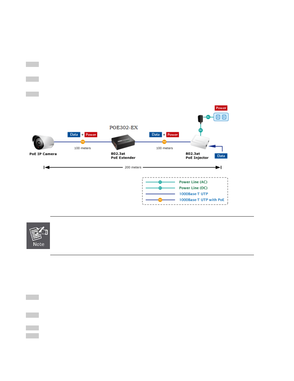
3.4 Multiple PoE Extender Installation
The POE302-EX PoE Extender supports multiple units, daisy-chain installation. They can be employed in series for even longer
distances based on remote PoE IP Camera or PoE Wireless Access Point power requirement.
Step 1: Connect the additional Cat.5/5e/6 cable from the “OUT” port of the first POE302-EX, the other end of the UTP cable be
used to connect to the “IN” port of remote / next POE302-EX.
Step 2: The “PoE OUT” LED indicator of the first POE302-EX will be steady to shows it is providing power to next PoE
Extender.
Step 3: The “PoE IN” LED on the next POE302-EX will steady on.
Step 4: Connect the additional Cat.5/5e/6 cable to the remote PoE powered device to the “OUT” port of next or third
POE302-EX.