5 cable connection – IC Realtime 2Mp Full HD 20x/30x Network PTZ Dome Camera (ICIP2001HD) User Manual
Page 34
28
5 Cable Connection
Multiple-function combination cable consists of network cable, audio/video port, RS485 port, alarm input,
output cable port. Please refer to the label for detailed information.
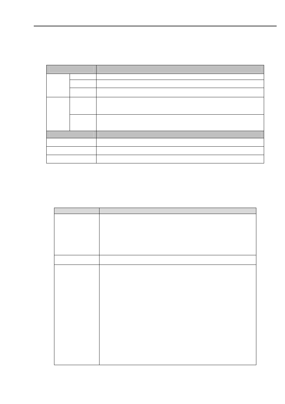
1) RS485 and audio/video port, power port and network port information is shown below:
Name
Function
A
485-A port. It is to control the speed dome built-in PTZ.
B
485-A port. It is to control the speed dome built-in PTZ.
485
GND Ground
end.
GND Ground
VIDEO
OUT
Video output port. You can connect this port if you want to use the
analog video output.
Name
Function
POWER
Power port. Please refer to the label for detailed information.
EARTH Ground
port.
LAN
Network port. Connect to the network cable.
z
Please refer to the label instruction for the alarm connection information of the multiple-function
combination cable.
z
You can connect 485 port if you want to use the RS485 to control the network speed dome.
Otherwise, you do not need to connect.
2.) Relay in/out interfaces is shown below:
Name
Function
Alarm out;1-2
z
When there is an alarm from current channel, system activates
relay or not.
z
Device default setup is NO. NO:Normal open alarm output.
For the default setup: 1-channel alarm input and 2-channel
alarm output is optional.
GND
Alarm input ground end.
Alarm in:1-7
z
2-channel alarm input. It is to receive relay signal from the
external alarm source. You can go to dome menu to activate
specified preset or patter.
z
When the activation mode is NO (normal open), dome alarms
when there is low voltage. High voltage will not activate the
alarm.
z
When the activation mode is NC (normal close), dome alarms
when there is high voltage. Low voltage will not activate the
alarm.
Note:
z
Dome alarm input message is ground mode.
z
Dome alarm input signal are two modes: normal open and
normal close.
z
For the default setup: 2-channel alarm input and 7-channel