Great Planes Tiger Moth 60 ARF - GPMA1330 User Manual
Page 19
❏
18. Drill a 3/16" hole through the firewall for the throttle
pushrod guide tube. Be certain to not drill into the tank! It
may be helpful to remove the engine for this step, so it does
not interfere with drilling the hole (or use an extended drill bit).
❏
19. Lightly sand then insert the 3/16" x 11-3/4"
[4.8mm x 298mm] throttle pushrod guide tube through the
hole in the firewall. Bend the 17-1/2" [445mm] throttle
pushrod if necessary. Attach a nylon clevis approximately 25
turns and add a silicone retainer. Then connect it to the
carburetor arm on the engine. Connect the opposite end of
the pushrod wire to the throttle servo with a screw-lock
pushrod connector.
❏
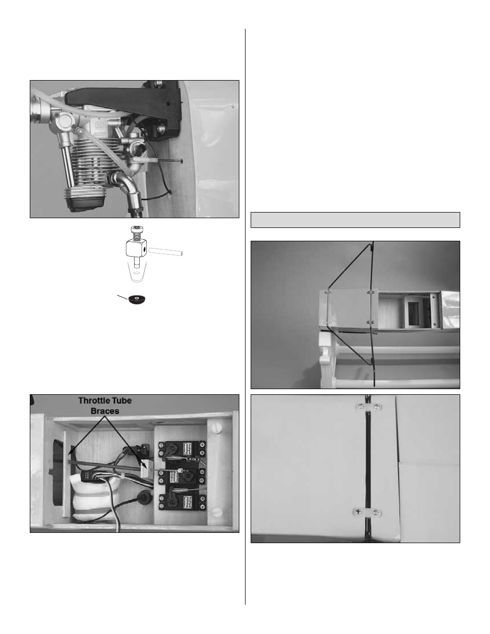
20. Make a brace for the aft end of the guide tube from
1/8" [3mm] scrap balsa or plywood (not included) and glue it
in place as shown. Also make another brace to fit across the
former as shown in the photo. You will have to slip the outer
tube through the braces or make them with a slot in order fit
them properly. Glue the tube into place with epoxy at both
braces and at the firewall.
❏
21. Set the carburetor to the closed position. Turn the
radio system on and move the throttle servo to the fully
closed position. Tighten the socket head cap screw in the
screw-lock pushrod connector. Cut off the excess pushrod
aft of the screw-lock pushrod connector.
❏
22. Make certain all the servo arms are secured to the
servos with the screws that came with them and that all the
clevises have retainers.
❏
23. Install your aileron extension wire, supplied with your
radio system into the receiver. Connect the Y-connector
(HCAM2751) to the aileron servo wires taped to the top of
the bottom wing. Be sure to tape or use heat shrink material
to secure these connections.
❏
1. Place the landing gear in the grooved hardwood
mounts at the bottom of the fuselage and mark the position
for the nylon landing gear straps as shown. Drill 1/16"
[1.6mm] holes in the locations for the straps and harden the
areas with thin CA. Secure the straps with #2 x 1/2" Phillips
head screws.
Install the Landing Gear
RETAINER
19