Great Planes PT-17 Stearman .91-1.20 ARF - GPMA1349 User Manual
Page 24
❏
3. On the right side of the fuselage, slide one wire into
the opening closest to the back of the fuselage. Install a
nylon control horn onto the clevis. Position the control horn
on the rudder, positioning it the same way you did with the
ailerons. Mark the location for the screw holes. Drill through
the marks you made with a 1/16" [1.6mm] drill bit, drilling
only into the plywood plate. Do not drill through the
rudder! Install and then remove two 2-56 x 5/8" [16mm]
machine screws. Apply a couple drops of thin CA into the
holes. Once the glue has cured, mount the horn and the
nylon mounting plate to the rudder with the screws.
❏
4. Install the two elevator pushrods using the same
procedure used for the rudder. Be sure when installing the
control horn on the right elevator that you install it so it
does not conflict with the rudder control horn.
❏
5. Place your rudder servo into the servo tray as shown,
positioning the last hole of the servo arm over the pushrod
wire. Drill a 1/16" [1.6mm] hole through each of the mounting
holes. Remove the servo, then install and remove a servo
mounting screw into each hole. Apply a couple drops of thin
CA into the holes to harden the threads. When the glue has
cured, permanently mount the servo to the servo tray.
❏
6. Center the rudder and the rudder servo, then install
the servo arm. At the point the pushrod wire intersects the
last hole in the servo arm make a mark. Bend the wire 90
degrees on that mark. Install a nylon FasLink and cut off the
excess wire the same as was done with the throttle servo.
❏
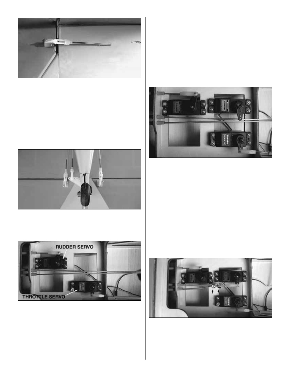
7. Place your elevator servo into the servo tray as
shown, positioning the last hole of the servo arm over the
inside pushrod wire. Drill a 1/16" [1.6mm] hole through each
of the mounting holes. Remove the servo, then install and
remove a servo mounting screw into each hole. Apply a
couple drops of thin CA into the holes to harden the threads.
When the glue has cured permanently, mount the servo to
the servo tray.
❏
8. Bend the outer elevator pushrod as shown. Cut off
the excess wire. Center both of the elevators, then center
the elevator servo. Secure the two pushrod wires with two
5/32" [4mm] wheel collars and 6-32 x 1/4" [6.4mm] socket
head cap screw. Attach the elevator pushrod to the servo
arm with a nylon FasLink using the same technique used on
the rudder and throttle.
24