Set the control throws, Balance the model (c.g.), Balance the model – Great Planes P-47 Thunderbolt GP/EP ARF - GPMA1479 User Manual
Page 22
22
IMPORTANT: The Combat P-47 ARF has been
extensively flown and tested to arrive at the throws at
which it flies best. Flying your model at these throws will
provide you with the greatest chance for successful first
flights. If, after you have become accustomed to the way
the P-47 flies, you would like to change the throws to suit
your taste, that is fine. However, too much control throw
could make the model difficult to control, so remember,
“more is not always better.”
Balance the Model (
c
.
g
.)
More than any other factor, the
C.G. (balance point) can
have the
greatest effect on how a model flies, and may
determine whether or not your first flight will be successful.
If you value this model and wish to enjoy it for many flights,
DO NOT OVERLOOK THIS IMPORTANT PROCEDURE.
A model that is not properly balanced will be unstable and
possibly unflyable.
At this stage the model should be in ready-to-fly condition
with all of the systems in place including the engine or
brushless motor, landing gear, and the radio system (and
battery pack if applicable).
o
1. Use a felt-tip pen or 1/8" [3mm]-wide tape to accurately
mark the C.G. on the top of the wing on both sides of the
fuselage. The recommended C.G. is located 2-1/4" [57mm]
back from the leading edge of the wing.
This is where your model should balance for the first
flights. Later, you may wish to experiment by shifting the
C.G. up to 3/16" [5.2mm] forward or 1/2" [12.7mm] back to
change the flying characteristics. Moving the C.G. forward
may improve the smoothness and stability, but the model
may then require more speed for takeoff and make it more
difficult to slow for landing. Moving the C.G. aft makes
the model more maneuverable, but could also cause it
to become too difficult to control. In any case,
start at
the recommended balance point and do not at any time
balance the model outside the specified range.
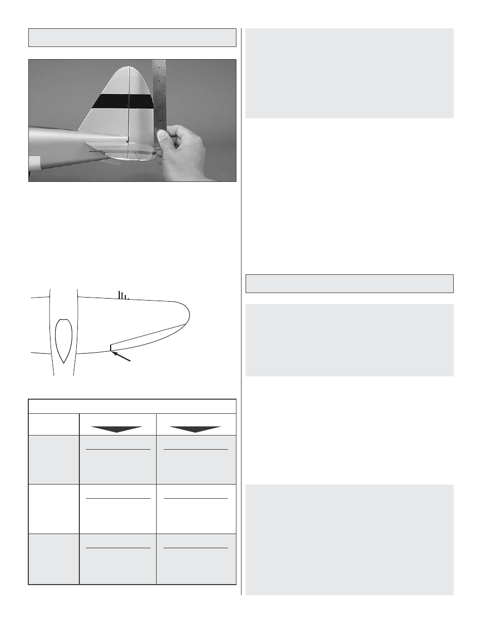
Set the Control Throws
Use a Great Planes AccuThrow (or a ruler) to accurately
measure and set the control throw of each control surface
as indicated in the chart that follows. If your radio does not
have dual rates, we recommend setting the throws at the
low rate setting.
NOTE: The throws are measured at the widest part of the
elevators and rudders. Aileron throws are to be measured
from the inboard portion of the aileron.
MEASURE AILERON
THROW AT THIS POINT
These are the recommended control surface throws:
ELEVATOR
HIGH RATE
LOW RATE
3/8”
[9.5mm]
10deg
Up
3/8”
[9.5mm]
10deg
Down
15/64”
[6mm]
7deg
Up
15/64”
[6mm]
7deg
Down
RUDDER
1”
[25.4mm]
28deg
Right
1”
[25.4mm]
28deg
Left
11/16”
[17.5mm]
17deg
Right
11/16”
[17.5mm]
17deg
Left
AILERONS
13/64”
[5.2mm]
9deg
Up
13/64”
[5.2mm]
9deg
Down
1/8”
[3.2mm]
5deg
Up
1/8”
[3.2mm]
5deg
Down