Great Planes Big Stik 60 ARF MonoKote - GPMA1226 User Manual
Page 15
❏
C. Mark servo hole locations on the tray, then drill
1/16" (1.5mm) pilot holes through each mark.
❏
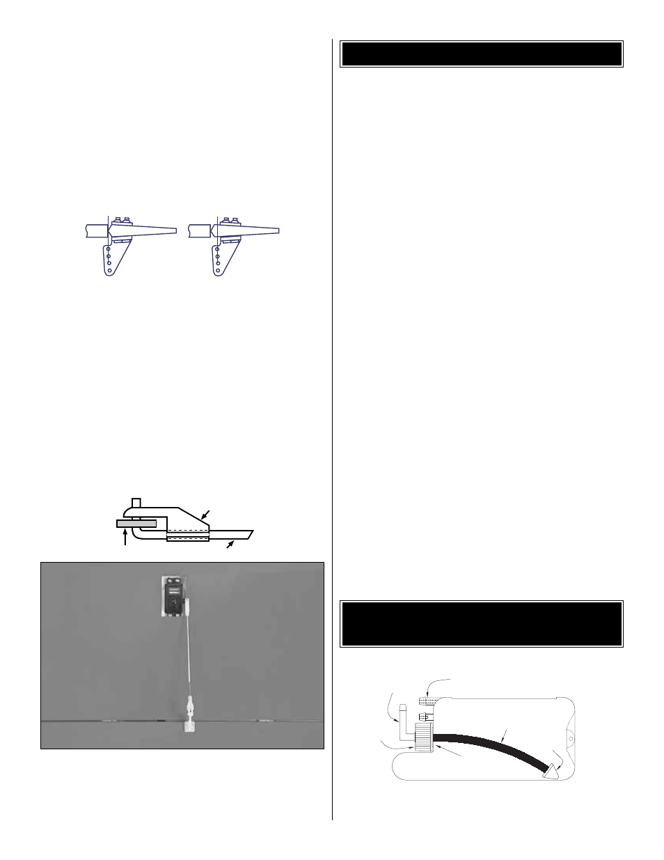
D. Mount the servos in both sides of the wing with
the screws provided with your radio system. Notice the
orientation when installing.
❏
E. Attach a 6" (150mm) servo extension lead (not
included with the kit) to each of the aileron servos. Tape
the extension to prevent it from pulling loose. Use the
string you installed earlier to pull the wire through the
wing and out the hole.
❏
16. Install the aileron nylon control horn in line with the
servo arm. Hold the horn in position and mark the location
of the mounting holes. Drill 3/32" (2.4mm) mounting holes
through the marks. Wick two to three drops of thin CA into
the holes to harden the underlying balsa, then re-drill the
holes. Attach the horns using #2 x 1/2" Screws and Nylon
Nut Plates. Do not overtighten the screws, crushing the
underlying balsa.
❏
17. Center the aileron trim and aileron servo by turning
the transmitter and receiver on. Mark the pushrod where it
crosses the servo arm. Enlarge the servo horn hole with a
5/64" (2mm) drill bit.
❏
18. Screw on a clevis and the silicone retainer to the
pushrod. Make a 90-degree bend in the pushrod on your
mark, then insert it through the enlarged hole in the servo
arm. Cut off the excess wire 3/8" (9.5mm) above the bend.
Secure the wire in place with a nylon FasLink.
❏
1. Install a Brass Screw-lock Pushrod Connector with the
4-40 x 1/8" Cap Screw on the servo arm. Snap the Nylon
Retainer onto the screw-lock pushrod connector post
beneath the servo horn.
❏
2. Assemble the Throttle Pushrod Wire by installing a
nylon clevis about 14 turns and a silicone retainer onto the
threaded end. Slide the throttle pushrod into the outer tube
located on the right side of the firewall.
❏
3. Bend the throttle pushrod as necessary to reach the
throttle arm without binding. When satisfied with the fit,
insert the pushrod through the screw-lock pushrod
connector on the servo. Connect the throttle on the engine,
snap the clevis closed, then slide the retainer in place.
❏
4. With the radio switched on, move the throttle and
control stick to the fully closed position. Manually close the
throttle on the carburetor completely. Tighten the cap screw
on the screw-lock connector. Check throttle operation with
the radio and make adjustments to the linkages as
necessary for smooth operation. Use the appropriate holes
in the servo and throttle arms to provide the correct amount
of throttle movement and to prevent the servo from binding
at its end point.
❏
1. Assemble the fuel tank as shown in this sketch.
Fuel Pick-up
Line
Clunk
Cap
Rubber Stopper
Fitting
Vent
FUEL TANK ASSEMBLY
AND INSTALLATION
THROTTLE PUSHROD INSTALLATION
FasLink
2-56 (.074") Pushrod Wire
Servo Horn
Correct
Incorrect
15