Great Planes PT-60 Kit - GPMA0119 User Manual
Page 17
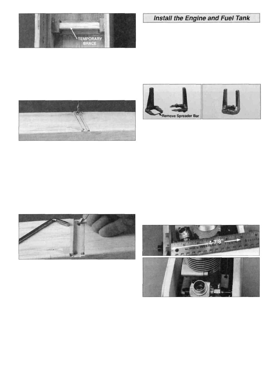
D 3 Use 30 minute epoxy to glue the 3/4" x 3/4" x 1/2"
hardwood landing gear blocks to the fuse sides and LG
rail in the recesses created by the landing gear doublers A
scrap balsa stick should be wedged between the blocks to
hold them in position while the epoxy cures
Note: You may work on the next section (engine & fuel
tank) while waiting for the epoxy to fully cure
D 4 After allowing the LG assembly to cure for a few
hours (overnight is best) fit the die cut 1/8 ply landing
gear drill guide into the groove in the rail flush with the
fuse sides as shown Drill a 3/32" pilot hole through the
rails and underlying blocks at each of the punch marks on
the guide Use care to make the holes as perpendicular to
the fuse bottom as possible Check the inside of the fuse to
make sure that the holes are straight and clearly in the
hardwood LG blocks then redrill the holes with a 3/16" bit,
making angular adjustments if necessary
D 5 Test fit the main landing gear. You need to carve a
small radius in the LG rail holes toward the center of the
fuse to allow the LG wire to fully seat in the holes Also, it is
helpful to file off the sharp edges at the ends of the LG
wire A f t e r fitting the LG in position, the LG may be
removed and set aside until final assembly.
The Great Planes adjustable engine mount is simple and
convenient to use It may be used to mount most 40 60
two stroke and 40 70 four stroke engines Nose gear
bearings are incorporated in the mount Because the nose
gear bearing holes are prednlled for 5/32" wire, you will
need to enlarge the holes by drilling them out with a 3/16"
or 13/64" bit If you have a numbered drill bit set the #11 bit
is perfect If you use a 3/16" bit wiggle the bit around to
create a slightly loose fit or the nose gear wire will be tight
Caution: Don't overdo the enlargement process!
D 1 Cut or break the spreader bar from each mount half
Carefully trim any extra material left by the spreader bar
from each mount half as the surface where the spreader
bars were attached must be smooth to allow the mount
halves to fit together Trim the flashing from any rough
edges if necessary Assemble the mount halves as shown
D 2 Temporarily install the engine mount on the firewall
using four #6 flat washers and four 6-32 x 1" machine
screws Don't tighten the screws completely until after the
engine has been positioned
D 3 Remove the needle valve from the engine, then position
the engine on the engine mount Slide the engine mount
halves apart until the engine mounting lugs will sit flat on the
rails Adjust the mount until the firewall centerline is centered
between the "tick" marks on the mount Tighten the 6-32
screws to hold the mount firmly in position against the firewall
NOTE: If you will be installing a 4 stroke engine you
need to plan ahead for servo location and pushrod
routing Refer to the sketch on page 34 and the fuselage
plans for the 2 stroke/4 stroke servo and pushrod setup
D 4 Position the engine so that the backplate of a spinner will
be 4-7/8" (124mm) in front of the firewall Carefully mark the
engine mounting holes on the rails with a sharpened piece
of wire or a pencil lead NOTE: If installing an 0S 70 4
stroke engine the engine will have to be slightly forward of the
recommended position to allow for the choke mechanism This
will not cause a balance problem and is quite acceptable
17