Install the hardware, Join the control surfaces final hookups & checks – Great Planes Extra 300S 60 Kit - GPMA0236 User Manual
Page 41
compatible with the clear canopy, test the paint on a
leftover piece of canopy material.
For painting the pilot we have discovered that acrylic water
base paints such as the types found at craft stores work
great. The acrylic paints look realistic on the pilot because
they are not glossy and best of all, they clean-up with water.
❏
1. Start with the elevators and stab. Cut the covering
from the hinge slots–don’t just slit the covering but remove
a small strip the size of the hinge slot.
❏
2. Drill a 3/32" hole 1/2" deep in the center of each hinge
slot. A high speed Dremel Multi-Tool works best for this. If
you use a slower speed drill, clean out the hinge slots with
your #11 blade.
❏
3. Without using any glue, test fit the hinges in the
elevators or stab. Do not glue the hinges yet. As you join
the elevators to the stab, confirm that the hinges are
equally inserted in the elevators and the stab. Insert a small
pin in the center of the hinges to keep them centered.
❏
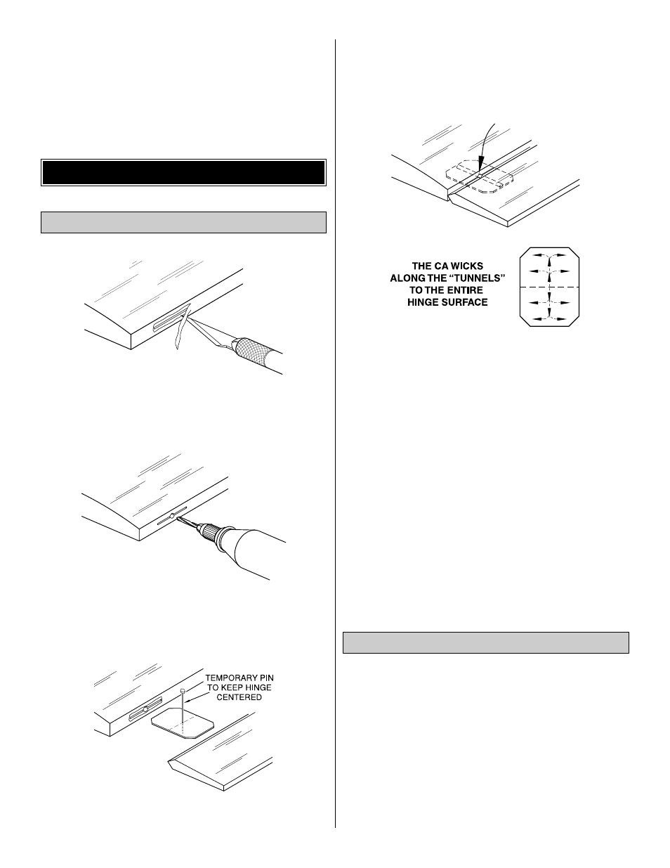
4. Remove the pin and add 6 drops of thin CA to the
center of all the hinges on both the top and the bottom.
Do not use accelerator on any of the hinges. Do not
glue the hinges with anything but thin CA and do not
attempt to glue one half of the hinge at a time with
medium or thick CA. They will not be properly secured
and the controls could separate while the model is
in flight.
❏
5. Join the rudder to the fin with the hinges and use
30-minute epoxy to simultaneously glue the tail gear wire in
the rudder and the tail gear bearing in the fuse. Do not glue
the nylon bearing to the rudder. Glue the hinges in position
with thin CA.
❏
6. Prepare the hinge slots in the ailerons the same way
you did for the tail surfaces. Glue the hinges with thin CA.
❏
1. Assemble the fuel tank per the manufacturer’s
instructions. Install it in the fuse with approximately 12" of
fuel line on the pickup and the vent lines on the tank.
❏
2. Install a 1" tail wheel with a 3/32" wheel collar.
❏
3. Install the wheels in the wheel pants, then mount the
wheel pants to the landing gear. Secure the 8-32 nuts with
a drop of thread lock.
❏
4. Mount the landing gear to the fuselage with the #8
x 5/8" truss head screws and #8 washers.
Install the Hardware
ASSEMBLE, THEN APPLY 6 DROPS
OF THIN CA TO CENTER
OF HINGE, ON BOTH SIDES
DRILL A 3/32" HOLE
1/2" DEEP, IN CENTER
OF HINGE SLOT
AWAY FROM THE SLOT
CUT THE COVERING
Join the Control Surfaces
FINAL HOOKUPS & CHECKS
41