Test run the motor/fan unit, Surface preparation, Install the fan unit – Great Planes F-16 Falcon EDF ARF - GPMA1801 User Manual
Page 8
8
❏
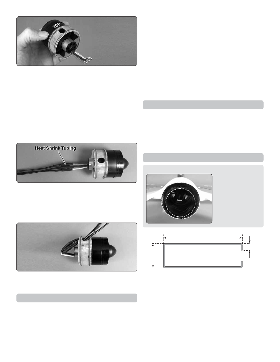
14. Test fi t but do not glue the cone adapter to the rear of
the fan housing. Note that the hole in the housing should be
180° from the side of the motor where the wires exit—this will
be the
top
of the unit. Once you have the housing and adapter
mated correctly, permanently glue the two together by adding
a few drops of thin CA to the seam around the
outside
. Also
apply a few drops of medium CA to each stator blade where
it contacts the inside of the adapter.
Note:
Apply the CA
sparingly and with care
. Otherwise it will run all over the place.
❏
15. Install the fan rotor onto the motor noting the orientation
you marked earlier (for minimal run out)—be certain to use
a small drop of thread locking compound on the 3mm screw.
❏
16. Cut the included heat shrink tubing into three equal
lengths. Connect the motor lead extensions to the motor wires.
Slide the heat shrink pieces onto the motor lead extensions
and use a heat source (heat gun or lighter) to shrink the
tubing around the connections in order to prevent them from
becoming inadvertently disconnected.
❏
17. Carefully slide the motor lead wires through the hole
in the top of the cone adapter as shown.
Test Run the Motor/Fan Unit
❏
1. You may perform either a brief test-run of the motor/fan
unit, or do the complete break-in procedure as described on
the back cover of the HyperFlow instruction manual. In either
case prepare to run the motor by connecting the ESC to
your receiver and to the motor wires coming from the motor.
Reverse the throttle channel in your transmitter and turn on
the transmitter. Connect your motor battery to the ESC.
❏
2. Follow all the precautions and run the motor at no more
than 1/4 throttle as described by the “PREPARE TO RUN
THE FAN” instructions on the back cover of the HyperFlow
fan instructions. (If the motor is turning backwards switch any
two of the motor wires with each other.) Check for vibration
and/or unusual noises and do not proceed until resolving
any problems.
❏
3. Continue with the rest of the break-in procedure until
the system is fully broken-in. Or, if you’re satisfi ed with the
way the unit is performing, stop now and mount the unit in
the fuselage as described in the next section. Be certain to
complete the break-in procedure before fl ying your F-16 for
the fi rst time.
Surface Preparation
There are several steps in this manual that require you to
glue parts to the fi berglass fuselage. Anytime this is done,
the fi berglass should fi rst be cleaned with a cloth dampened
with denatured alcohol, sanded with 220 grit sandpaper, then
cleaned again with denatured alcohol. Doing this will ensure
a strong glue bond.
Install the Fan Unit
DESIGNER NOTE: The aft end of the tail cone is not
centered within the aft
end of the fuselage and
this can be seen by
looking at the plane
from the back side. This
is an intentional part of
the design to maximize
fl ight performance of
the aircraft.
ROTOR PULLER
1" [25mm]
3-1/2" [90mm]
1/4" [6mm]
It’s a good idea to test fi t the fan without glue so you can
make sure it fi ts properly. Once permanently installed, the
fan unit will not be possible to remove. However, the motor
may be removed by taking off the fan rotor, unscrewing the
motor mounting screws and taking the motor out the back
through the tail cone. Once out the tail cone, the motor wires
can be disconnected. If you can’t get a good enough grip with
your fi ngers to pull the fan rotor off the adapter, make a
rotor
puller
from an 8-1/2" [215mm] piece of 2-56 pushrod wire
by bending it as shown. Insert the short hooks on the ends
of the puller under the fan hub and pull
.