Get the model ready to fly set the control throws, Balance the model (c.g.) – Great Planes F-16 Falcon EDF ARF - GPMA1801 User Manual
Page 19
19
GET THE MODEL READY TO FLY
Set the Control Throws
To ensure a successful fi rst fl ight it is
critical
that the F-16
is set up according to the control throws specifi ed in this
manual. The throws have been determined through actual
fl ight testing and accurate record-keeping, allowing the
model to perform in the manner in which it was intended.
If, after you have become accustomed to the way the F-16
fl ies, you would like to change the throws to suit your taste,
that is fi ne. However, too much control throw could make the
model too responsive and diffi cult to control, so remember,
“more is not always better.”
Use a Great Planes AccuThrow (or a ruler) to accurately
measure and set the control throw of each control surface
as indicated in the chart that follows. If your radio does not
have dual rates, we recommend setting the throws at the
low
rate setting.
NOTE
: The throws are measured at the
widest part
of the
elevators, rudder and ailerons.
These are the recommended control surface throws:
ELEV
A
TOR
R
UDDER
AILER
ONS
LOW RATE
3/16"
[5mm] 9°
Up & Down
1/8"
[3mm] 7°
Up & Down
1/4"
[6mm] 14°
Right & Left
HIGH RATE
5/16"
[8mm] 14°
Up & Down
3/16"
[5mm] 10°
Up & Down
11/32"
[9mm] 20°
Right & Left
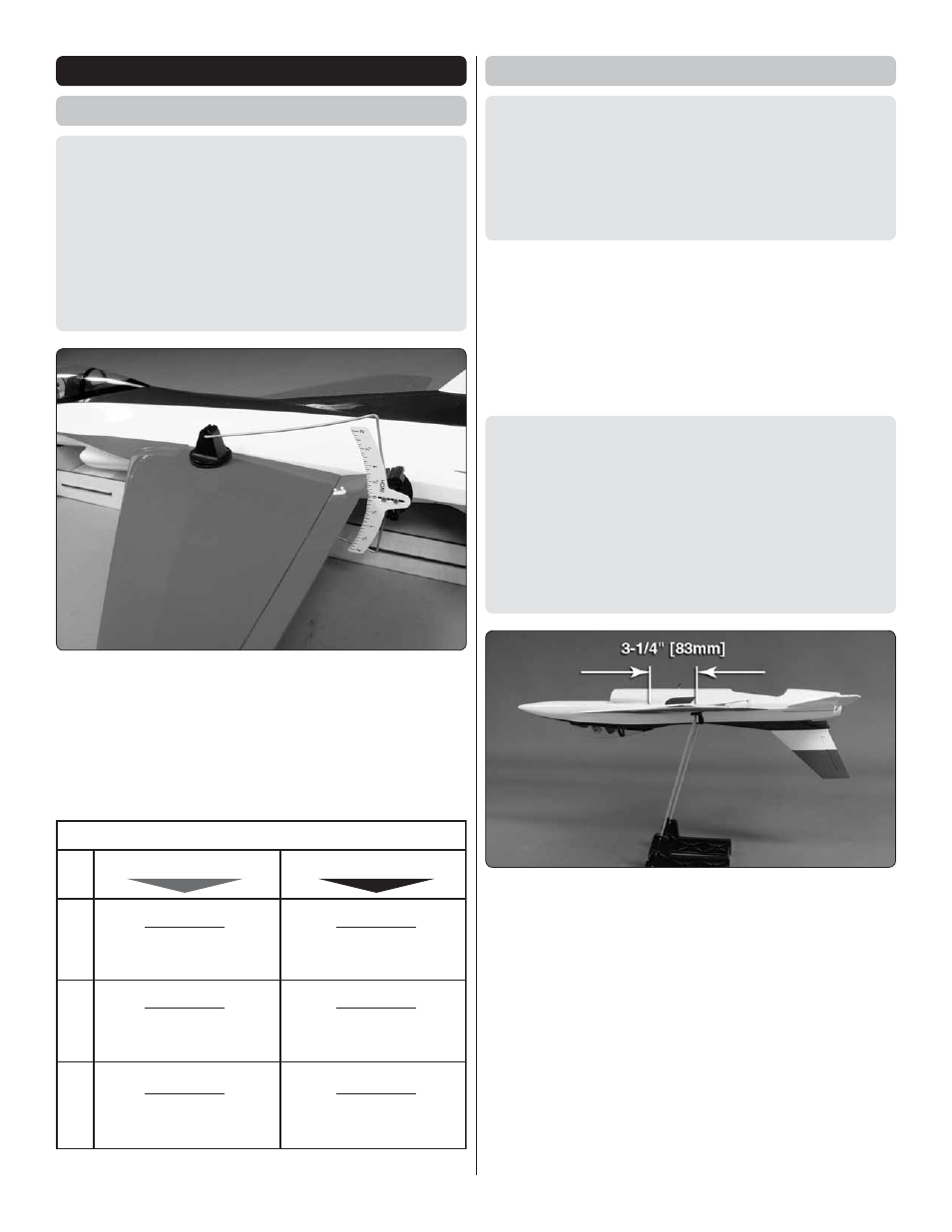
Balance the Model (C.G.)
More than any other factor, the
C.G.
(balance point) can
have the
greatest
effect on how a model fl ies, and may
determine whether or not your fi rst fl ight will be successful.
If you value this model and wish to enjoy it for many fl ights,
DO NOT OVERLOOK THIS IMPORTANT PROCEDURE.
A model that is not properly balanced will be unstable and
possibly unfl yable.
At this stage the model should be in ready-to-fl y condition
with all of the systems in place including the battery, receiver,
and canopy hatch.
❏
1. Use a felt-tip pen or 1/8" [3mm]-wide tape to accurately
mark the C.G. on the top of the wing on both sides of the
fuselage. The C.G. is located 3-1/4" [83mm] back from the
leading edge of the wing where it meets the fuselage.
This is where your model should balance for the fi rst fl ights.
Later, you may wish to experiment by shifting the C.G. up
to 1/4" [6mm] forward or 3/8" [9.5mm] back to change the
fl ying characteristics. Moving the C.G. forward may improve
the smoothness and stability, but the model may then be
more diffi cult to slow for landing requiring a longer approach.
Moving the C.G. aft allows for slower landing speeds but
could also cause it to become too diffi cult to control. In any
case,
start at the recommended balance point
and do not
at any time balance the model outside the specifi ed range.
❏
2. With all parts of the model installed (ready to fl y) including
the hatch and battery, place the model upside down on a Great
Planes CG Machine, or lift it at the balance point you marked.
❏
3. If the tail drops, the model is “tail heavy” and the battery
pack and/or receiver must be shifted forward. If the nose drops,
the model is “nose heavy” and the battery pack and/or receiver
must be shifted aft. If possible, relocate the battery pack and
receiver to minimize or eliminate any additional ballast required.
Our test samples balanced within the specifi ed C.G. range
using the recommended battery and servos without additional
ballast. If additional weight is required, however, nose weight
may be easily added by using Great Planes (GPMQ4485)
“stick-on” lead. A good place to add stick-on nose weight is
inside the nose cone or underneath the gap between the aft
end of the tail fi n and the fuselage.