Great Planes ElectroStik EP RxR - GPMA7500 User Manual
Page 12
12
Set the Control Throws
To ensure a successful fi rst fl ight, fl y your ElectroStik EP
RXR set up only according to the C.G. and control surface
throws specifi ed in this manual. The throws and C.G. are not
arbitrary, but have been determined through extensive testing
and accurate record-keeping. This provides you with the best
chance for success and enjoyable fi rst fl ights that should be
surprise-free. Additionally, the throws and C.G. shown are
true, real data which will allow the model to perform in the
manner in which it was intended when fl own by a pilot of the
skill level for which it was intended. DO NOT OVERLOOK
THESE IMPORTANT PROCEDURES. A model that is not
properly setup may be unstable and possibly unfl yable.
Use a Great Planes AccuThrow (or a ruler) to accurately
measure and set the control throw of each control surface as
indicated in the chart that follows. If your radio does not have
dual rates, we recommend setting the throws at the low rate
setting. Note: The throws are measured at the widest part
of the elevators, rudder and ailerons.
These are the recommended control surface throws:
High Rate
Low Rate
ELEVATOR: 1/4" [6.4mm] 10 deg up
1/8" [3.2mm] 5 deg up
1/4" [6.4mm] 10 deg down
1/8" [3.2mm] 5 deg down
RUDDER:
1-1/8" [28.6mm] 50 deg right
5/8" [15.9mm] 25 deg right
1-1/8" [28.6mm] 50 deg left
5/8" [15.9mm] 25 deg left
AILERONS: 1/2" [12.7mm] 20 deg up
3/8" [9.5mm] 15 deg up
1/2" [12.7mm] 20 deg down
3/8" [9.5mm] 15 deg down
Balance the Model (C.G.)
At this stage the model should be in ready-to-fl y condition
with all of the systems in place including the motor, landing
gear, covering, motor battery, and the radio system.
❏
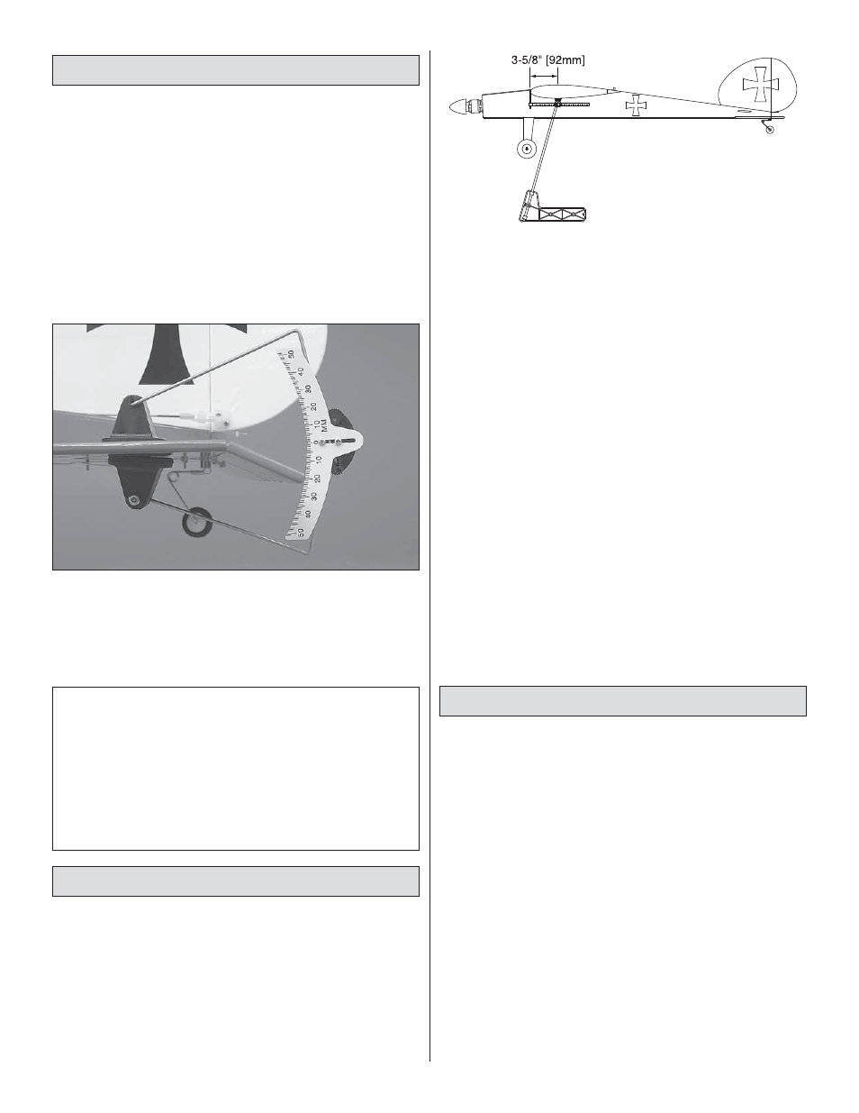
1. Use a felt-tip pen or 1/8" [3mm]-wide tape to accurately
mark the C.G. on the bottom of the wing on both sides of the
fuselage. The C.G. is located 3-5/8" [92mm] back from the
LE of the wing.
❏
2. With the wing attached to the fuselage, all parts of the
model installed (ready to fl y) and a motor battery on board,
place the model on a Great Planes C.G. Machine, or lift it at
the balance point you marked.
❏
3. If the tail drops, the model is “tail heavy” and the battery
pack and/or receiver must be shifted forward or weight must
be added to the nose to balance. If the nose drops, the model
is “nose heavy” and the battery pack and/or receiver must be
shifted aft or weight must be added to the tail to balance. If
possible, relocate the battery pack and receiver to minimize
or eliminate any additional ballast required. If additional
weight is required, use Great Planes (GPMQ4485) “stick-on”
lead. A good place to add stick-on nose weight is to the
fi rewall. Begin by placing incrementally increasing amounts
of weight on the fuselage over the fi rewall until the model
balances. Once you have determined the amount of weight
required, it can be permanently attached. If required, tail
weight may be added under the stab at the fuselage. Note:
Do not rely upon the adhesive on the back of the lead weight
to permanently hold it in place. Over time, the adhesive may
soften and cause the weight to fall off. Use thin CA, RTV
silicone or epoxy to permanently hold the weight in place.
❏
4. IMPORTANT: If you found it necessary to add any weight,
recheck the C.G. after the weight has been installed.
Balance the Model Laterally
❏
1. With the wing level, have an assistant help you lift the
model by the engine propeller shaft and the bottom of the
fuselage under the TE of the fi n. Do this several times.
❏
2. If one wing always drops when you lift the model, it
means that side is heavy. Balance the airplane by adding
weight to the other wing tip. An airplane that has been laterally
balanced will track better in loops and other maneuvers.